Select an external AC EMI filter from the installed equipment’s input conditions, thermal environment and interference problem, then retest the complete assembly. A supply’s EMC report and a filter’s catalog insertion loss are useful evidence, but they do not establish that their combination meets the equipment’s requirements.
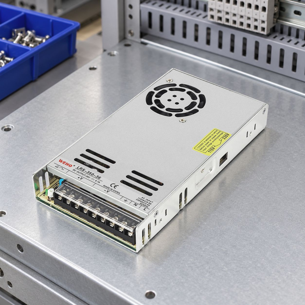
This guide covers a manufactured filter module at the AC mains entrance of an SMPS-powered product. It does not cover designing a DC-DC input LC network or adding an output ripple filter. Those changes have different component and interaction questions; keep the DC-DC input-filter review separate.
Record the actual emissions problem
Start with the test report or repeatable pre-compliance observation. Name the equipment port, operating mode, frequency region, applicable limits, measurement configuration and margin. A statement that “the supply is noisy” leaves too many decisions unresolved: a startup transient, DC ripple and conducted emissions at an AC port are different observations.
TDK-Lambda’s external-filter FAQ explains why a supply’s laboratory configuration can differ from the finished system. Actual loads and cable arrangements can create a need for additional filtering. Use the equipment evidence to choose candidate filters rather than assuming the supply’s component-level result transfers unchanged.
Read the full supply report when it is available, including its loads, auxiliary components and cable arrangement. For that procurement task, see auditing an EMC Class A or Class B report. The letter by itself does not identify the test required for the final machine.
Screen voltage, current and temperature
Use the filter manufacturer’s specified AC voltage, frequency, supply-system and operating conditions. Review the highest relevant steady input current of the complete protected branch, including other connected devices. Supply output watts divided by one nominal AC voltage is not a complete input-current specification.
Then apply the candidate’s own temperature derating. SCHURTER’s power-entry-module guidance emphasizes that combined inlet, switch, fuse and filter functions each have thermal constraints. A rating stated at one ambient temperature is not automatically available in a hotter equipment bay.
For a hypothetical screening example, assume the documented maximum continuous branch current is 3.4 A at the intended low-line condition, and the filter’s local ambient is 55°C. Candidate A is labeled 4 A, but assume its manufacturer’s curve permits only 75% of that current at 55°C: 4 × 0.75 = 3.0 A. It fails this current screen even though 3.4 A is below the headline 4 A rating.
Suppose candidate B is labeled 6 A and its own curve permits 70% at the same temperature: 6 × 0.70 = 4.2 A. It passes this one screen because 3.4 A is below 4.2 A. The percentages are invented example inputs, not general derating rules. Passing this comparison does not qualify B’s leakage, mounting, safety documentation or EMC result.
On small screens, scroll sideways to compare the candidate evidence.
| Screen | Record for the actual candidate | Reason to hold selection |
|---|---|---|
| Electrical rating | Voltage, frequency, supply arrangement and required current. | Rating or permitted arrangement does not cover the project. |
| Thermal rating | Local ambient, derating curve and installation conditions. | Available current is insufficient at the actual temperature. |
| Leakage/protection | Declared conditions, equipment budget and protective arrangement. | Added filter changes a required protective condition. |
| Mechanical fit | Mounting, terminals, access and cable separation. | The documented installation cannot be reproduced. |
| Technical result | Relevant attenuation data and assembled-equipment measurements. | Only a catalog curve supports the proposed result. |
Include leakage and protective arrangements
A filter can change the equipment’s earth-leakage behavior. Include it in the existing review of the supply, other filters and connected equipment. Record the voltage, frequency and measurement conditions attached to each declared value; do not treat unlike catalog numbers as an exact prediction of the final measurement.
দ TDK EMC-filter technical guide distinguishes comparison values from measurement of the assembled installation. Check the final arrangement against the applicable equipment requirements and protective devices. A lower-leakage candidate can also change attenuation, so both questions remain in the selection record.
If an RCD is part of the equipment’s protective arrangement, use the system leakage-current budget as a starting point and verify the installed result. Do not disconnect protective earth to make an emissions or leakage observation look better. Missing protection evidence should be resolved by the responsible equipment designer.
Treat installation as part of the filter
The selected component needs an installation that can be reproduced in production. Review its stated LINE/LOAD orientation, mounting arrangement, protective connection, terminal method, environmental limits and any required spacing. Qualified personnel should follow the exact filter instructions; this article does not supply a universal mains wiring diagram.
Plan where incoming and outgoing cables run and how the filter relates to the equipment enclosure. The TDK technical guide treats protective-conductor connection and the filter’s interference-suppression reference connection as distinct functions. Preserve both according to the applicable instructions rather than assuming any convenient mounting screw serves every purpose.
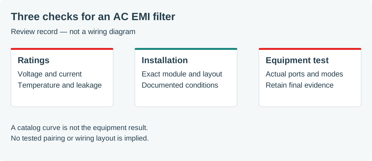
Also check non-EMC consequences after adding the module: equipment startup, repeated restart, input protection and local temperature. A candidate that improves one measured frequency region still needs to operate within its documented electrical and thermal envelope.
Retest and freeze the resulting configuration
A catalog insertion-loss curve is a comparison tool. The TDK technical guide explains that standardized source/load impedances used for those curves differ from real applications. Consequently, do not subtract a catalog attenuation number directly from the machine’s previous emission result and present the difference as a measured compliance margin.
Keep a before-and-after record with the same equipment mode, ports, load, harness arrangement and measurement method. Ask the test laboratory which operating configurations and additional tests are required after the change. Capture any deterioration in other frequency regions as well as the improvement that motivated the filter.
For release, retain the exact filter suffix, supply revision, installation drawing, photographs, thermal/current evidence and final reports. A different leakage variant, connector, cable routing or mounting surface is a configuration change worth reviewing. The procurement outcome is a documented equipment configuration, not simply an extra part placed on the bill of materials.