Direct answer: If a sensor’s output changes but a PLC misses counts, compare the shortest actual ON and OFF pulse widths with the sensor response, input filter, module capture and data-transfer requirements. A visible indicator or a sensor frequency rating alone does not prove that each transition reaches the program. Test the complete chain at the highest production speed.
Start with the pulse at the input
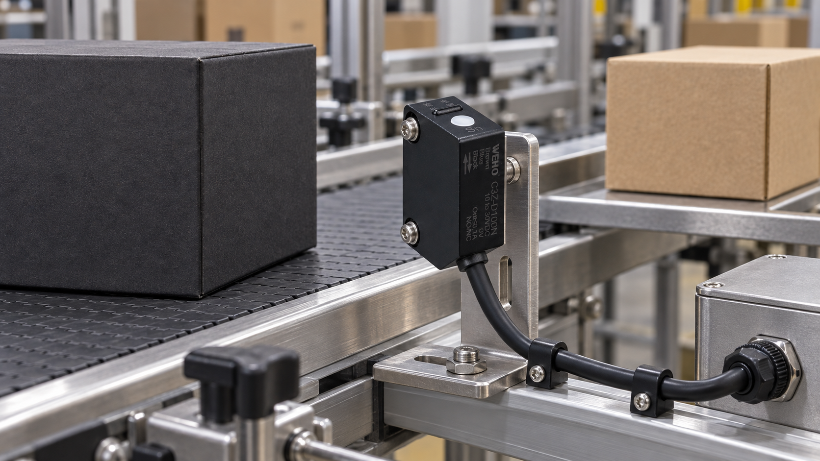
The sensor, target geometry, mounting and speed determine a real pulse. Measure the signal at the PLC input using equipment suitable for the voltage and pulse width. Check both states: a fast ON pulse can be filtered out, while a short OFF gap can merge two objects into one continuous input. The mechanical target’s effective detection length can differ from its physical length, particularly for reflective or irregular objects.
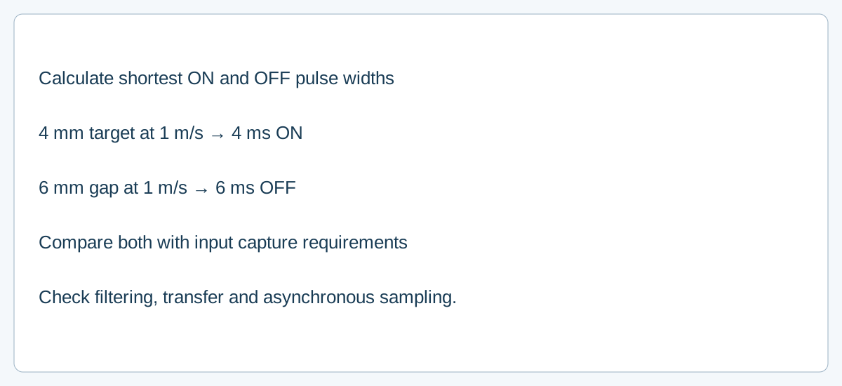
Worked example: translate target geometry into time
Assume a steady line speed of 1 m/s (1,000 mm/s), an effective detection length of 4 mm and a gap of 6 mm. These are hypothetical values, not a test or a WEHO specification.
| আইটেম | Calculation | Result |
|---|---|---|
| ON width | 4 mm ÷ 1,000 mm/s | 4 ms |
| OFF width | 6 mm ÷ 1,000 mm/s | 6 ms |
| Period and rate | 10 mm ÷ 1,000 mm/s | 10 ms; 100 cycles/s |
If an example input requires at least 5 ms in each state under its specified conditions, the 4 ms ON pulse fails that screen even though the 6 ms OFF period passes. A capture input specified at 1 ms minimum could pass this one width comparison, but sensor response, asynchronous transfer, count capacity and program logic still need review. Do not interpret 100 cycles/s as a guaranteed allowable sensor rating.
Follow the event through each stage
- Sensor: check the actual model’s response and output characteristics, target, background, mounting and worst-case supply; verify the real waveform.
- Electrical interface: check output type, PLC input thresholds, loading, shared reference and cable conditions. Cable capacitance and the output drive can alter signal edges, so measure the waveform at the receiving thresholds rather than assuming an ideal square wave. A correct input type and clean levels are prerequisites for a timing analysis.
- Input filter: find the configured ON and OFF filter behavior and its documented minimum pulse requirement. Increasing filtering can suppress noise and also reject legitimate short pulses.
- Capture and transfer: determine whether the module samples cyclically, latches events, or provides a dedicated counter, and how results reach the controller. A short pulse can fall between asynchronous samples.
- Program: check edge detection, task execution, counter limits and resets. Compare the captured total with a trusted independent count at full speed.
Rockwell’s M850 input documentation describes fast latching on that controller; its 1769 high-speed counter manual documents filters for that module. These features and settings do not automatically apply to another controller.
What can improve capture?
Depending on the equipment, options include changing target geometry or speed, using an appropriately specified faster sensor, adjusting an approved filter, using a hardware latch or a suitable high-speed counter, or revising the acquisition architecture. Select the remedy only after the input signal and the module’s guaranteed behavior are known. Excessively shortening a filter can introduce false counts from electrical noise.
Document the power and measurement context
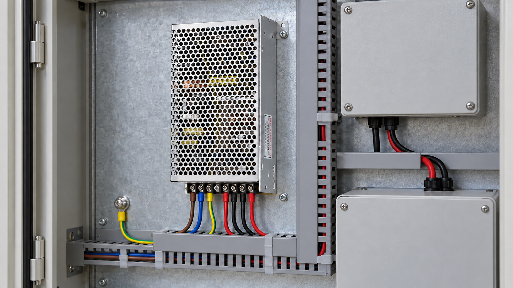
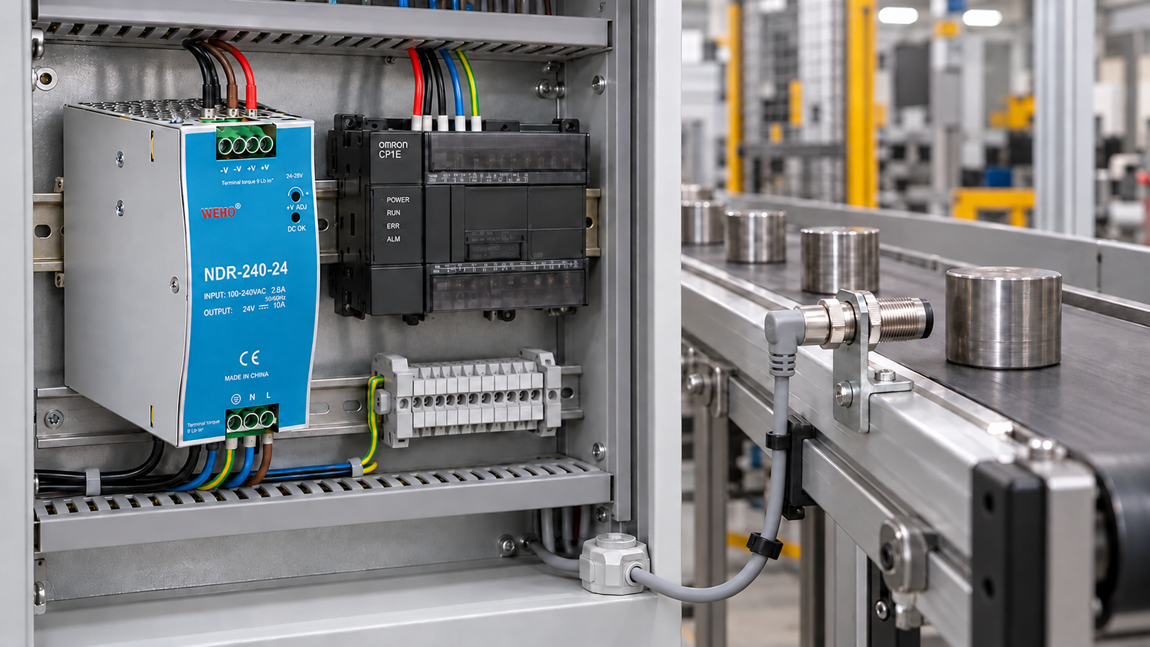
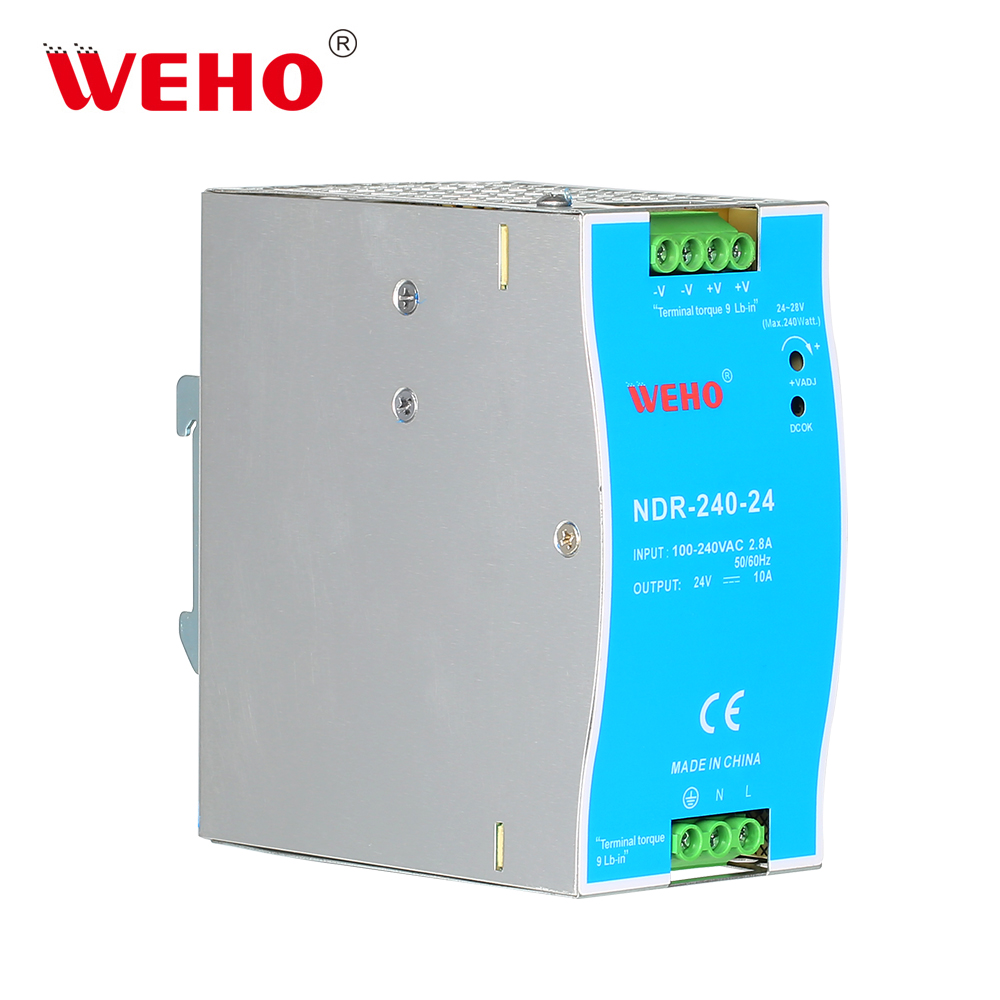
The pictured WEHO NDR DIN-rail supply can be reviewed as a cabinet power component. It is not a sensor, PLC or pulse-capture device; the photo does not establish counting performance. Specify the actual sensor and controller separately and check their documents before committing to the design.
Frequently asked questions
Is an input pulse longer than one PLC scan always sufficient?
No universal one-scan rule covers every architecture. Module filters, asynchronous input updates, task timing and guaranteed capture rules differ. Use the specific device documentation and verify the whole chain.
Does a higher sensor frequency rating guarantee no missed counts?
No. The rated switching-frequency test conditions may not match the target geometry or duty cycle, and the receiving input and program may still miss transitions.
Send WEHO your cabinet supply requirements and provide the sensor and PLC model numbers, target geometry, line speed, measured shortest pulses and input configuration for a documented component review. WEHO এর সাথে যোগাযোগ করুন.