Evaluate the air entering the inverter in its final compartment, not only the temperature in the room. Exhaust that returns to the intake can raise the local cooling-air temperature even when a fan is visibly running.
This guide gives an integrator a thermal observation map for the WEHO WHP5000W inverter family. It addresses compartment design and repeatable thermal review; it does not report product temperatures or assign an unsupported clearance or full-load ambient limit.
Map where cooling air can enter and leave
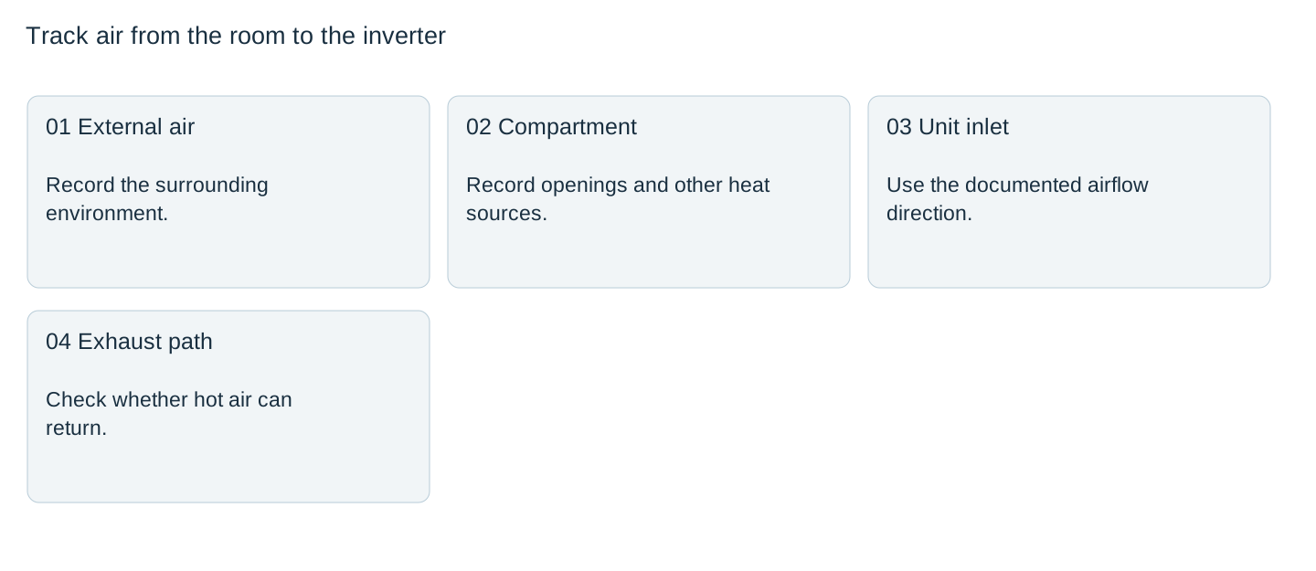
Start with the matching installation instructions and identify the unit’s actual intake and exhaust behavior. Do not infer fan direction from a front photograph. Draw the compartment openings, nearby heat sources, partitions, stored items and likely service obstructions around that documented path.
Separate the room from the compartment and the compartment from the inlet. An open cabinet door during a demonstration changes the air route and may remove the restriction present during normal operation. Evaluate the released configuration, including covers and filters.
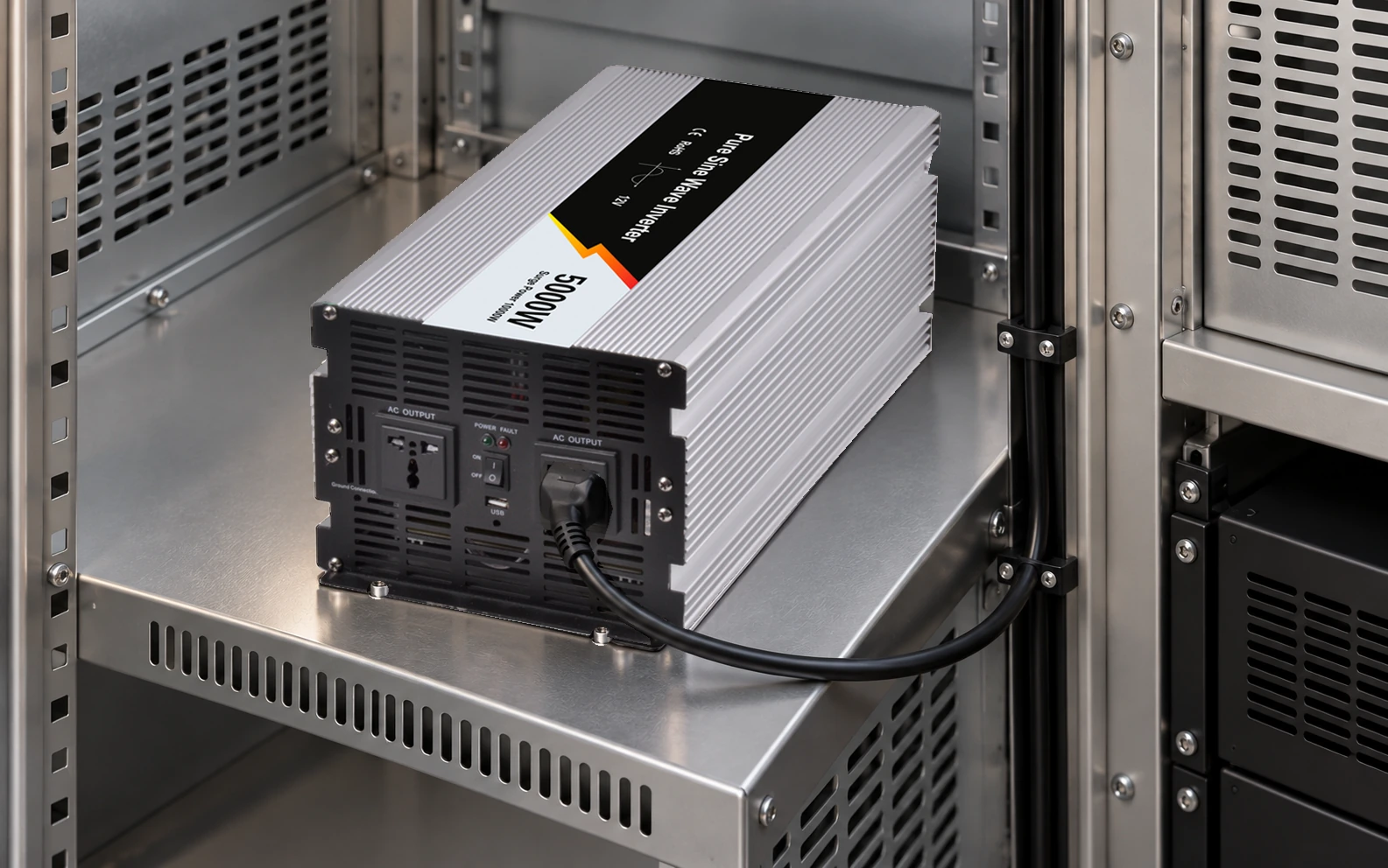
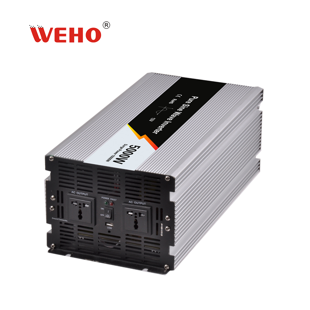
The official 5000 W image shows the ribbed case, front vents and two outlets. Those visible features support product identification. They do not determine internal airflow, mounting orientation or required clearances.
Choose measurement points that can distinguish recirculation
| Point | Reason for including it | Record with it |
|---|---|---|
| Room / external air | Separates general environment from compartment rise | Location and nearby heat sources |
| Compartment supply air | Shows restriction or accumulated heat | Door/filter/fan configuration |
| Documented inverter inlet | Shows the air available to the unit | Sensor position without obstructing flow |
| Documented exhaust region | Helps compare heat leaving and returning | Position and operating state |
Use sensors and a method appropriate to the expected conditions. A shiny enclosure can complicate infrared surface readings, and case temperature is not the same quantity as inlet-air temperature. Define what each reported reading represents.

Estimate heat only to understand the design question
For an assumed 3000 W AC load and assumed 90% conversion efficiency, inverter loss would be3000×(1/0.90−1)=333 W. At an assumed 85% efficiency, the same calculation gives approximately 529 W. These are hypothetical heat estimates, not WHP efficiency points.
The example shows why a single maximum-efficiency claim is insufficient for compartment design. Add heat from other actual equipment and obtain the inverter’s applicable loss/derating information. A more accurate heat budget does not, by itself, determine the airflow or prove acceptable internal temperatures.
Do not use the 5000 W family name as a statement that 5000 W is continuously available in every enclosure. Request the conditions attached to the offered unit’s continuous rating.
Observe the complete intended duty
Record load power, battery input, output configuration and temperature over the agreed representative cycle. Include neighboring equipment that operates at the same time. Continue for the period justified by the project’s thermal criteria rather than ending as soon as the fan starts.
Victron’s Sun Inverter installation guidance illustrates that location, orientation and ventilation conditions are product-specific requirements. Its dimensions and temperature limits must not be copied onto WHP hardware.
If inlet temperature rises above the room while exhaust remains nearby, investigate the air route and repeat the affected observation after a controlled design change. Correlation is useful evidence; it is not a complete measurement of internal component temperatures.
Freeze the configuration that was actually evaluated
Retain opening dimensions, filter condition, fan settings, load duty, sensor locations and ambient conditions with the observations. Compare results with the applicable inverter and receiver limits. A protection shutdown is an abnormal outcome to investigate, not a target that defines the acceptable thermal boundary.
Do not solve a blocked path by removing guards, drilling the product case or defeating thermal protection. Compartment changes and supplementary cooling require an appropriate mechanical/electrical review.
After release, identify which stored items and service alterations could obstruct airflow. Reassess a filter, partition, fan, neighboring heat source or load-duty change. This preserves the useful result: a known compartment configuration and a traceable thermal observation, rather than “the fan was running.”
Review the final compartment conditions
Send WEHO the WHP5000W configuration, compartment drawings, intended duty, surrounding heat sources and observation-point map. Request the matching installation, cooling and continuous-output conditions for that review.
Inverter compartment thermal record
| Time / state | Room air | Compartment / inlet air | Exhaust region | Load / observation / decision |
|---|---|---|---|---|
Blank project worksheet. Enter verified project data; example calculations above are not measurements.