

Key Engineering Takeaways
- Evaluate each LED branch connector at the current it actually carries, with its selected contacts, cable and enclosure conditions.
- Contact loss is localized: P = I²R does not predict a connector’s temperature without thermal evidence.
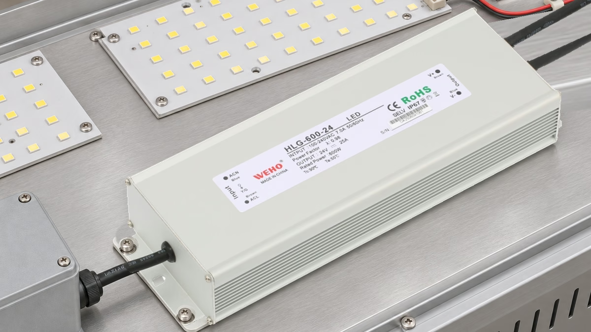
- HLG-600-24 is listed at 24 V, 25 A and 600 W; its output rating does not approve downstream connectors or branch protection.
- Retain voltage-drop, temperature and mechanical evidence for the same connection configuration rather than approving a connector from its headline current rating alone.
Why can a connector matter when the driver has sufficient power?
A driver can satisfy the source-side current requirement while one downstream connection introduces unacceptable voltage loss or localized heating. For a lighting-system OEM, the relevant decision is whether the complete connection assembly is suitable for its actual branch duty and installation conditions.
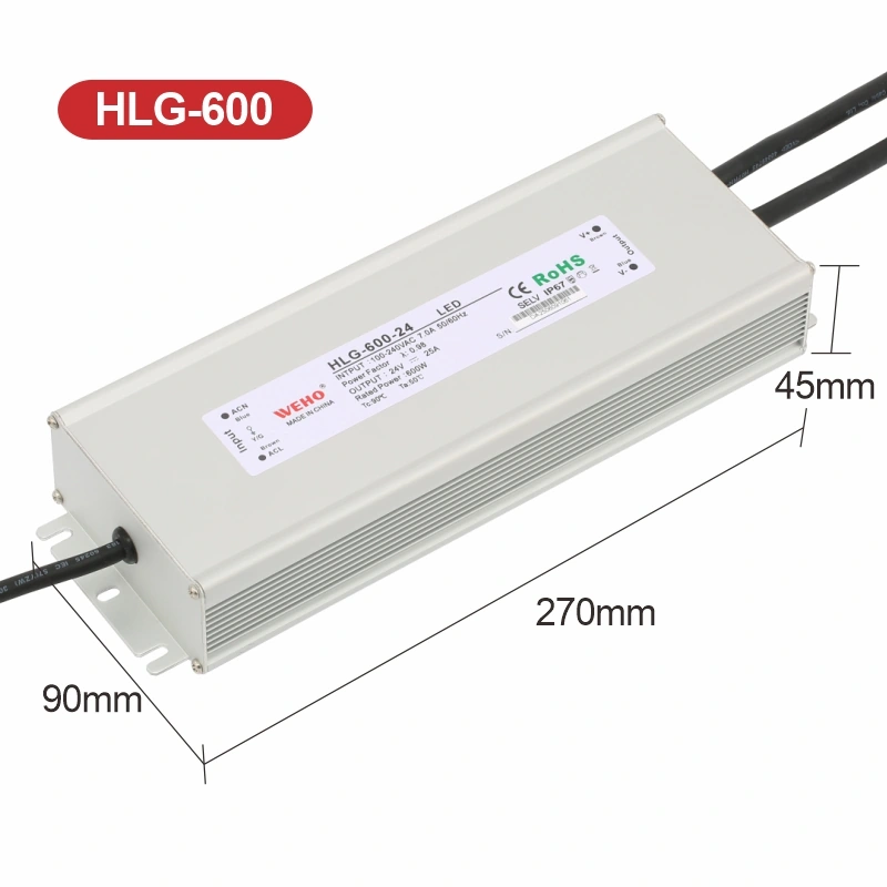
দ HLG-600-24 product and output reference identifies a listed 24 V, 25 A, 600 W source. Those ratings describe the supply under its applicable conditions. They do not assign 25 A capability to a connector, a small branch conductor or an arbitrary wiring arrangement.
This article isolates the connector decision. It does not select a branch fuse, prescribe a termination method or calculate a universal maximum LED-cable distance. The numerical comparisons are hypothetical engineering examples rather than measured driver or connector performance.
What resistance belongs in the connector calculation?
Use the resistance of the actual current path through the connection being evaluated. For a two-conductor DC branch, the outgoing and return contacts both contribute to the complete loop. State whether a quoted resistance represents one contact, one pole, a complete mated interface or a measured multi-element assembly.
The term “connector resistance” is otherwise ambiguous. A test lead, crimp, terminal, solder joint or cable segment may be included in a measurement depending on where the probes are placed. Define the measurement boundaries before comparing results, and keep conductor loss separate when it has already been calculated elsewhere.
For a steady current I and a defined contact resistance R, voltage drop is ΔV = I × R and dissipated power is P = I² × R. These expressions describe electrical loss at the stated operating point. They do not establish a material limit, temperature-rise criterion or environmental rating.
Resistance can depend on contact condition, assembly, current and temperature. Use the selected connector’s applicable information and representative evidence rather than assuming a single room-temperature resistance remains fixed throughout service. A catalog’s maximum or typical value also needs its stated test method and conditions.
How do two otherwise similar branch connections compare?
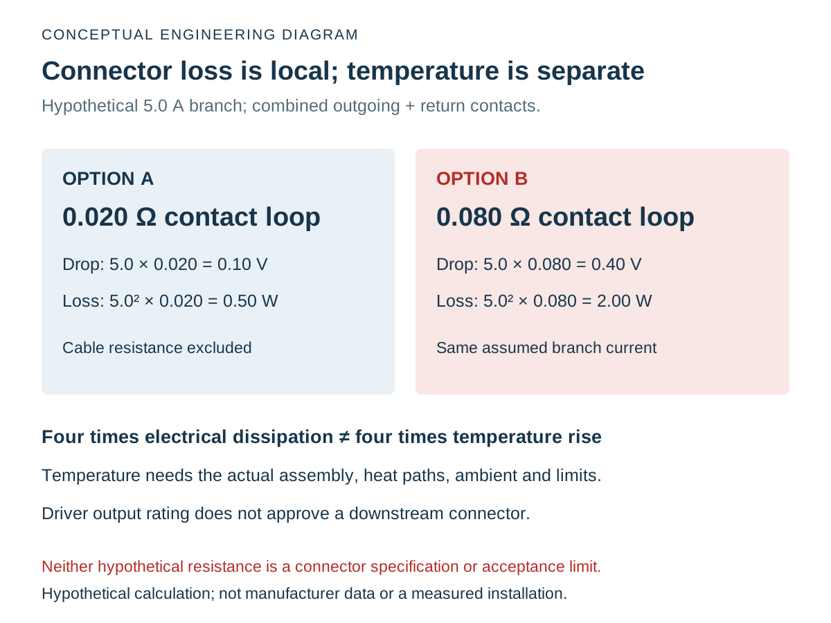
Compare connections at the same branch current and with clearly defined electrical boundaries. The following Hypothetical Connector-Loss Example assumes a 5.0 A steady branch. The resistance values apply to the combined outgoing and return contacts of one defined mated interface; cable resistance is excluded from this table.
Assume Option A has 0.020 Ω combined contact resistance and Option B has 0.080 Ω under the selected comparison condition. Neither value is a WEHO connector specification, a test result or a recommended acceptance limit.
| Quantity | Option A | Option B | Interpretation |
|---|---|---|---|
| Branch current | 5.0 A | 5.0 A | Same assumed current in the complete contact loop |
| Combined contact resistance | 0.020 Ω | 0.080 Ω | Outgoing plus return contacts; not one contact each |
| Contact-loop drop | 5.0 × 0.020 = 0.10 V | 5.0 × 0.080 = 0.40 V | Fourfold voltage loss at the same current |
| Contact-loop dissipation | 5.0² × 0.020 = 0.50 W | 5.0² × 0.080 = 2.00 W | Fourfold electrical heating power, not fourfold temperature rise |
| Percentage of assumed 24 V source | 0.10 ÷ 24 × 100 = 0.42% | 0.40 ÷ 24 × 100 = 1.67% | Connector contribution only, excluding the remaining branch |
The larger loss can be significant even when the branch remains below the driver’s total output rating. However, neither option receives approval from these calculations alone. Actual contact and housing temperatures depend on how heat leaves the contacts, the surrounding enclosure, nearby heat sources and the assembly’s permitted limits.
The current relationship also matters. If Option A’s assumed resistance remained 0.020 Ω and current increased from 5.0 A to 10.0 A, calculated drop would double to 0.20 V while calculated dissipation would rise to 2.00 W. That is a conditional arithmetic comparison, not evidence that Option A is rated for 10 A.
Do not multiply one branch’s current across every connector in a distribution system. A common feeder connector can carry several simultaneous branch currents, while a connector after the split carries its own branch current. Identify that position before assigning the value of I to the calculation.
Swipe horizontally on a small screen, or open the full-size diagram.
Why does a current rating need the complete assembly context?
A connector’s usable current depends on the conditions attached to its applicable rating and the selected assembly. Confirm the actual contact, housing, pole count, conductor and termination configuration rather than transferring a number from a different member of the same connector family.
দ HLG-600-24 documented source configuration does not close that downstream review. The supply’s fixed lead, a splice, a branch connector and the luminaire input each have their own identity and requirements. Keep the relevant component documents tied to the wiring revision.
| Evidence group | What to identify | What the review should establish |
|---|---|---|
| Current and thermal conditions | Actual duty, simultaneous currents, ambient and neighboring heat | Applicable component limits and representative temperature evidence |
| Contact and termination | Exact part numbers, conductor, preparation and assembly method | Instructions followed and the intended configuration inspected |
| Electrical-loss boundary | Probe locations, included contacts and excluded conductor portions | Drop and resistance figures are comparable and not double-counted |
| Mechanical and exposure conditions | Retention, strain management, mating state and exposure | Connection remains suitable through the defined handling and service conditions |
| Equipment protection | Branch wiring and protective arrangement | Equipment design protects the actual downstream circuit; supply wattage is insufficient evidence |
Environmental protection remains a separate boundary. A supply’s IP marking does not automatically protect its cut leads or an added connector. A connector’s protection may also depend on the exact mating state, seals, cable selection and assembly. Verify the intended configuration instead of copying the driver’s housing marking into the harness drawing.
How should the connector qualification record be built?
Build the record around the same connection assembly, defined test conditions and acceptance criteria. Obtain the relevant component limits before testing. An observation such as “it feels warm” cannot replace a documented temperature measurement or an applicable criterion.
- Identify the connection under review. Record both mating halves, contact parts, conductor and termination method. Capture the supply, branch and wiring revisions so the result cannot be transferred silently to another build.
- Define the electrical duty. Record the relevant steady and changing currents, shared-feed combinations and ambient conditions. State which observations are requirements, assumptions or measured operating values.
- Define measurement boundaries. Mark where voltage is measured and which contacts or joints the result includes. Use a suitable qualified method; do not infer a small contact drop from unrelated instrument readings or undocumented probe locations.
- Evaluate temperature separately. Record the measurement locations, ambient reference, assembly state and operating duration required by the test plan. Compare with the applicable component limits; do not calculate degrees of temperature rise directly from watts without a validated thermal model.
- Check repeatability and changes. Retain inspection and test evidence for the defined assembly. Reassess affected conditions after a connector substitution, conductor change, enclosure revision or duty change rather than inheriting an unrelated pass.
Perform electrical and mechanical test work through the equipment’s appropriate procedures and qualified personnel. The calculations here are a design screen, not instructions to disturb an energized connection or bypass protective measures during diagnosis.
A localized connector finding should lead to a configuration-specific correction and retest. It should not automatically become an instruction to increase the supply voltage or fit a larger driver. Those changes can affect other loads while leaving the underlying termination or contact problem unresolved.
What should accompany a connection-system enquiry?
Send WEHO the branch and connector arrangement with the exact supply model, currents, connector parts, conductor selection and installation conditions. Include the defined measurement points, observed voltage loss or temperature data, and the relevant assembly revision. Ask for the applicable interface information without assuming that a driver supplier has approved an unspecified downstream connector.
Engineering FAQ
Does a 25 A supply rating make every branch connector suitable for 25 A?
No. The supply rating does not establish a downstream connector’s current capability or protect every branch conductor. Evaluate the actual connector assembly, its operating conditions and the equipment’s protective arrangement independently.
Does four times the contact loss mean four times the temperature rise?
No. Four times I²R loss is four times the calculated electrical dissipation under the stated assumptions. Temperature rise also depends on the assembly’s heat paths and conditions, so it needs applicable thermal evidence or a validated thermal model.
Should both positive and return contacts be included?
Yes, when evaluating the complete two-conductor connection loop. State the boundary and include each contributing series contact once. Do not double a value that already represents the combined outgoing and return path.
Can a larger driver fix a poor connector contact?
A larger driver does not establish a correction for excessive contact resistance, poor termination or an unsuitable connector assembly. Identify and correct the actual connection problem, then recheck the affected electrical, thermal and protective conditions.