A small control board does not automatically make power-supply selection simple. The enclosure may be tight, several receivers may share one output, and a low average load may still hide startup or switching demand. For buyers comparing an LRS-35W or LRS-50W power supply, the useful starting point is the exact ordered model and its installation interface, not the family wattage alone.
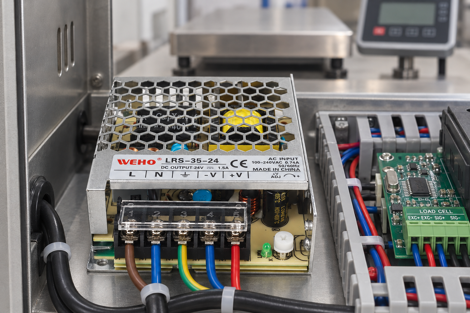
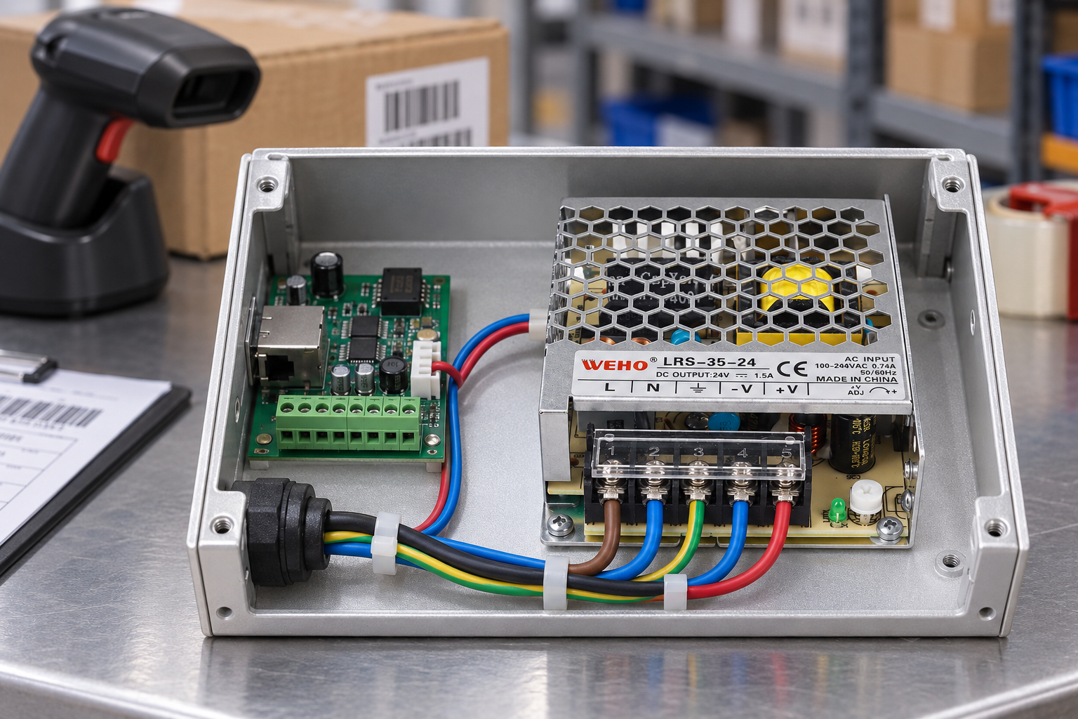
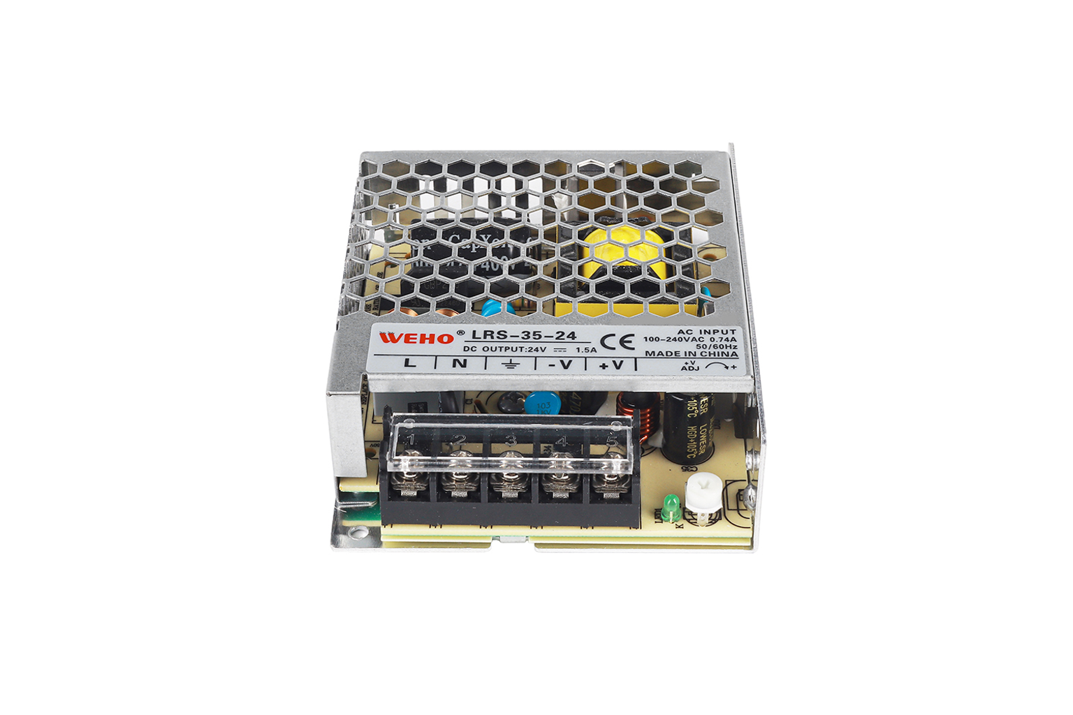
This review uses the source-identified WEHO LRS-35-24 as the physical example. Its original label states 24V DC, 1.5A, and 100–240VAC 0.74A 50/60Hz. The five-position, screw-mounted chassis is shown in proposed weighing-indicator and barcode-interface compartments. Those applications illustrate an integration review; they do not establish receiver compatibility or a performed electrical test.
Start the small-load budget with the exact output
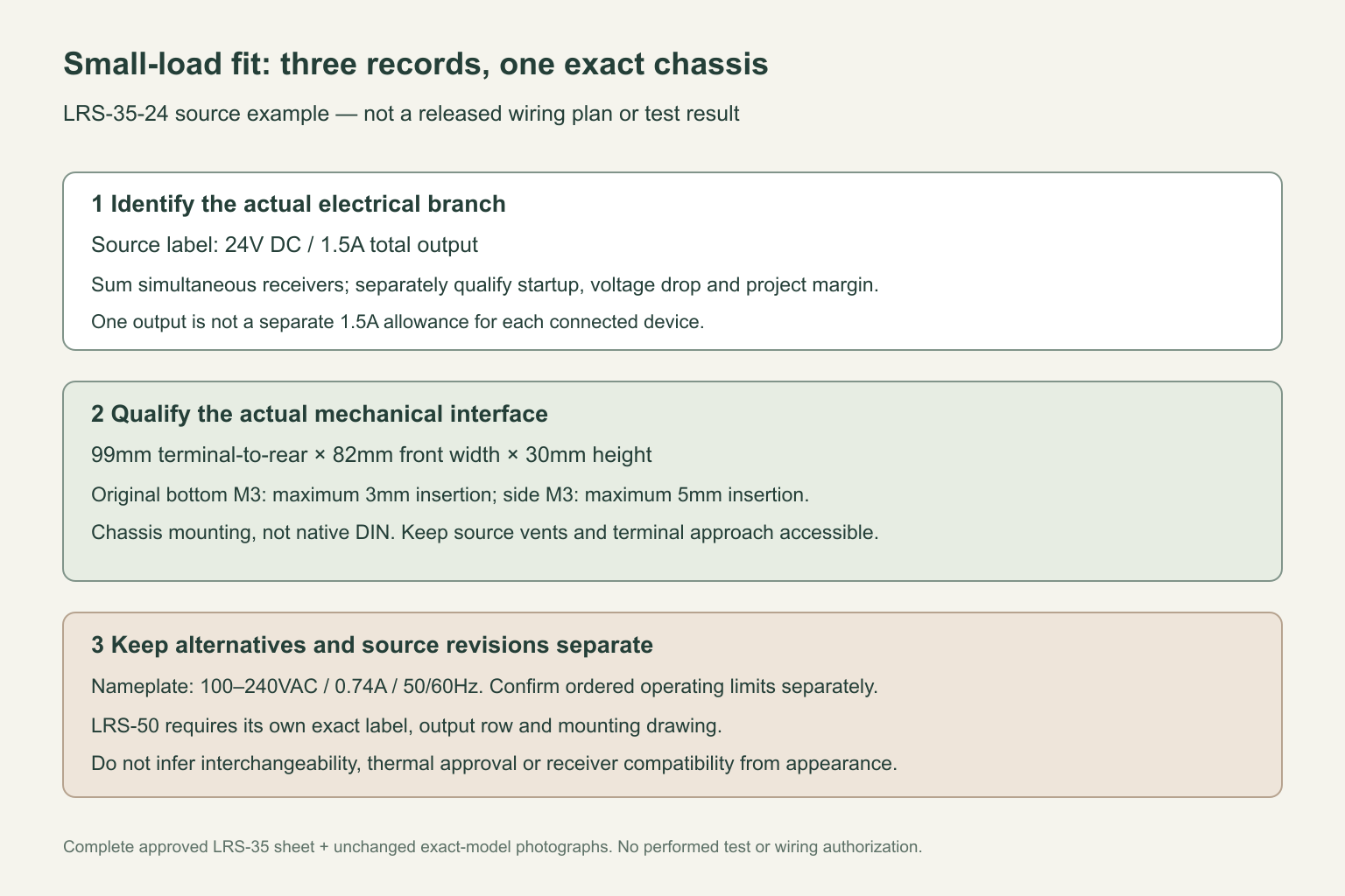
For this specimen, 1.5A is the documented output-current value. List every receiver on that 24V branch, including interface electronics, indicators, sensors and accessories. Record normal demand, startup demand, simultaneous operating states and the conditions attached to each equipment rating. Do not treat several connected receivers as separate 1.5A allowances.
For example, three hypothetical receivers drawing 0.65A, 0.25A and 0.10A concurrently add to 1.00A. This arithmetic is only a first screen: it says nothing about their startup behavior, allowable voltage drop or required design margin. Replace those example numbers with equipment documentation and measurements before approving the supply. A motor, solenoid or heater should not be assigned to this electronics branch merely because it appears nearby.
The series name and the exact row should remain separate records. The source sheet calls the family LRS-35W, while the selected label and row give 24V and 1.5A. Multiplying those values produces 36W arithmetically; it is not permission to relabel the product or substitute a new declared power rating.
Keep nameplate identity separate from revision-dependent limits
The photographed input line is 100–240VAC 0.74A 50/60Hz. The complete approved sheet lists a wider family operating input range of 85–264VAC and a 47–63Hz frequency range. An older public document uses different range limits. Preserve the photographed identity literally, and confirm the applicable specification revision for the ordered unit before using an extended operating limit.
This distinction also matters when a purchase request simply says “24V small power supply.” Record the full suffix, label photograph, specification revision and actual installation feed. The nominal output does not demonstrate that every receiver accepts the supply’s adjustment range, and the input-current label is not a universal branch-protection selection rule.
Check the chassis interface before releasing the enclosure
The complete drawing gives a 99mm terminal-to-rear length, 82mm terminal-face width and 30mm height. The mounting details identify bottom M3 screw engagement up to 3mm and side M3 engagement up to 5mm. Use the corresponding source-defined locations and insertion limits when designing the mounting plate; do not replace them with a convenient hole elsewhere in the casing.
The LRS-35-24 is a ventilated metal chassis, not a native DIN-rail supply. The proposed assemblies sit flush on a horizontal floor using the source-defined chassis interface; confirm the exact hole and fastener arrangement against the approved drawing. The images do not establish hidden screw engagement depth. A nearby rail may carry separate terminal or distribution hardware; that does not turn the supply into a rail-mounted product.
Reserve access to the terminal guard, screwdriver approach and conductor-entry faces, as well as the space needed for the actual loom. Keep the roof and source side vents unobstructed. A dimensional fit is not a thermal approval: assess the finished enclosure, orientation, ambient conditions and surrounding heat sources against the ordered specification and the project’s acceptance procedure. No clearance distance or enclosure-temperature result is assumed here.
Map the five connections without inventing extra channels
The actual left-to-right terminal legend is L, N, protective earth, −V and +V. There are five physical screw-clamp positions under the transparent guard. Conductors enter the real clamp mouths below the screw heads, not the screw-access holes, ventilation openings or adjustment aperture.
The DC pair supplies one documented output. Distribution to multiple devices needs an equipment-specific circuit plan, suitable conductor sizing and protection, and a total-load review. The generated assembly scenes are explanatory illustrations, not issued wiring instructions. Final AC connection, protective-earth implementation and testing belong to the qualified equipment assembly process.
The small +V ADJ feature is also not an operator control for changing between nominal variants. Any setpoint change requires the ordered revision’s limits, each receiver’s permitted input range and defined measurement points. Do not use an attractive illustration as evidence of a measured or released setting.
Compare LRS-35W and LRS-50W as separate purchase records
Do not infer an LRS-50 variant’s current, envelope or mounting pattern from these LRS-35-24 photographs. Request its own full-model label, electrical table and mechanical drawing. A larger family name may lead to a different physical or electrical interface, and a shared series appearance is not interchangeability evidence.
A useful procurement handoff contains the exact model, receiver-load record, applicable input limits, mounting drawing, loom-access layout and acceptance checks. For a compact weighing indicator or barcode interface, this makes the decision repeatable: a documented electronics branch, an actual chassis interface and a separately qualified alternative, without assuming that all small enclosed supplies are interchangeable.