Power-supply hold-up time is the interval that stored energy keeps the output within a defined voltage limit after input power is lost, under stated conditions. A DC UPS adds a managed energy-storage path for a specified continuity objective. Choose between the existing supply, a buffer module, and a DC UPS from the interruption duration, load timeline, minimum valid voltage, and recovery requirement. Begin with the event at the load terminals: a brief mains dip, a controlled shutdown, or continued operation until input returns.

Πίνακας περιεχομένων
Separate hold-up, transfer, and backup duration
A control cabinet can have three different timing requirements. First, its AC-DC supply may need to bridge a short input interruption. Second, a storage module may have to take over without the DC load crossing its minimum input voltage. Third, the stored energy may have to support the equipment until input returns or a shutdown completes.
| Question | Relevant boundary | Evidence needed |
|---|---|---|
| How long does the supply bridge input loss? | Defined input-loss event to output-voltage endpoint | Minimum or typical hold-up value, input, load, temperature, and endpoint definition |
| Does the load survive takeover? | Voltage at the specified load terminals during the transition | Transfer behavior with actual wiring, load dynamics, and device tolerances |
| How long can storage support the load? | Storage-ready state to the required end of service | Usable storage capacity, discharge limit, load profile, conversion losses, temperature, and aging condition |
| When is another event covered? | Recovery of the required energy reserve | Recharge behavior, source capacity, and readiness criteria |
A hold-up figure needs its load, input condition, voltage endpoint, and typical or guaranteed status. For a published example of that reporting format, see the external power-supply datasheet, revision 1.4, section 7. Compare the stated test point with the equipment requirement.
For a detailed method focused on the existing supply, use the WEHO hold-up-time test guide. Here, the next task is choosing the continuity architecture after the load and event are defined.
Write the interruption as a load timeline
“Keep the controller alive” is incomplete. Decide whether communications, I/O, valves, brakes, storage writes, and restart logic must also remain active. A device that remains energized can still lose its intended function if another required part resets.
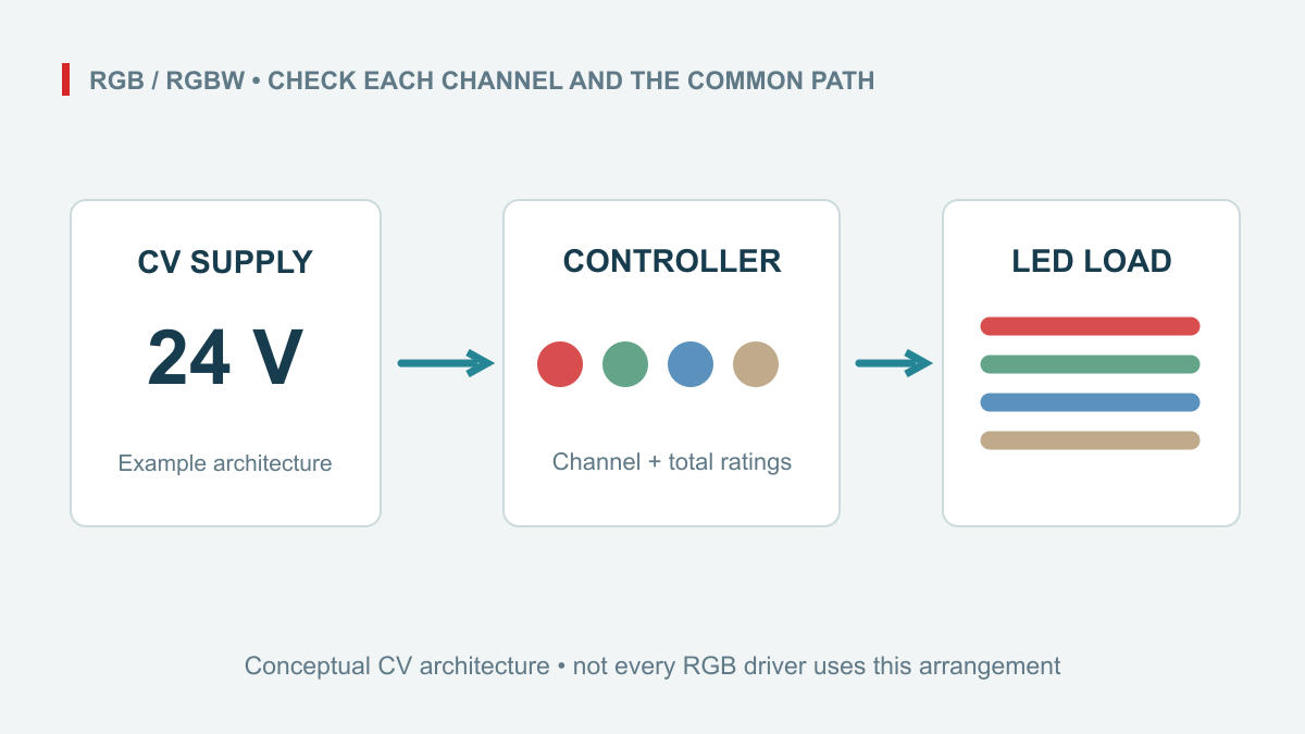
For a hypothetical 24 V control system, assume the full critical load consumes 72 W during the first 2 seconds of input loss. The machine then sheds nonessential loads and needs 24 W for another 18 seconds to finish a controlled shutdown. These figures are design assumptions, not measured WEHO results. The required continuity interval is 20 seconds.

Required load energy = (72 W × 2 s) + (24 W × 18 s) = 576 J = 0.160 Wh
At an assumed constant 24 V, the two stages correspond to 3 A and 1 A. If the DC bus changes in storage mode and the loads behave approximately as constant-power loads, calculate current at the lowest permitted bus voltage instead. At 21.6 V, the 72 W stage would draw about 3.33 A before distribution losses.
Use a shorter event to see the architecture boundary: a project may require riding through a 50–200 ms interruption without shutdown, while this example needs a full 20 s shutdown sequence. Those are example requirements, not product-duration bands. Compare each event with the supply’s documented hold-up at the actual load; if it falls short, evaluate a buffer or DC UPS and test the takeover voltage at the load.
Choose storage from the service requirement
| Option | Useful reason to evaluate it | Decision that still needs evidence |
|---|---|---|
| Existing supply hold-up | Its documented and validated performance may cover the complete required brief event | Does the load-terminal voltage stay valid at every required operating point? |
| Capacitor buffer | Short, frequent events or a defined brief shutdown task | Usable energy over the voltage window, peak current, recharge time, and environmental limits |
| Battery-backed DC UPS | A longer continuity interval or service objective that needs managed battery storage | Compatible battery, discharge curves, temperature, aging, cutoff, charging, and maintenance |
The time scale helps shortlist an architecture. Internal AC-DC hold-up commonly addresses events measured in tens of milliseconds. Electrolytic-capacitor buffers extend short-event support into milliseconds or seconds, while larger supercapacitor systems can support longer shutdown tasks. Battery UPS systems are worth evaluating for sustained operation measured in minutes or hours. These ranges overlap as load changes: select from the candidate’s current, energy, voltage, and recharge curves. The referenced explanation of capacitor buffering and its battery-versus-capacitor comparison illustrate the distinction. A stated hold-up time alone does not establish compliance with a voltage-dip standard.
For the hypothetical 576 J load requirement, assume 90% efficiency through the selected storage-to-load path. Storage must then deliver 576 J ÷ 0.90 = 640 J, or about 0.178 Wh. This is the energy demand for the stated event; it excludes any additional reserve, aging allowance, standby consumption, or repeated-event requirement.
For an ideal capacitor comparison only, usable energy is E = ½C(Vhigh² − Vlow²). An assumed 28 V to 22 V storage window and 640 J would require C = 2 × 640 ÷ (28² − 22²) ≈ 4.27 F. Use this ideal value to compare energy scale, then select a rated module from its permitted voltage window, topology, capacitance tolerance, series resistance, current limits, and temperature data.
Check usable runtime and readiness separately
For a battery UPS, use the exact manufacturer’s supported battery and runtime data. Converting nominal volts × ampere-hours into watt-hours is useful for an initial energy inventory, but it does not establish usable runtime at the required discharge rate and cutoff. Charging and discharge behavior must also match the battery chemistry.
For an example of a fully qualified runtime table, the external DC-UPS datasheet, revision 2.4, section 5 states battery condition, temperature, output conditions, battery choice, and aging considerations. Apply the equivalent conditions from the selected system’s own documentation.
During recharge, the AC-DC source may need to supply the operating load and storage charging simultaneously. Check the DC UPS input behavior and source current at the actual bus voltage, including conversion losses. A unit that keeps the load running can still lack enough spare input power to restore the reserve within the required time.
Specify whether a second interruption can occur before full recharge. Define what “ready” means for the next required event, how that state is signaled, and what the equipment does while reserve is inadequate. A maximum-runtime claim at full charge does not answer a repeated-interruption requirement.
Review the exact WEHO backup product boundary
For an SC-120 battery-charge supply inquiry, request the current full-model specification and supported battery arrangement before comparing it with the application’s timeline. Use the product and document links below to define the review. Include transfer behavior, battery-mode output regulation, and required backup duration. Verify whether the output follows the discharging battery voltage, less internal path drop, or is actively regulated; then compare the resulting minimum voltage at the load terminals with the equipment’s requirements.
Keep the load output, charging output, battery connection, and common reference distinct in the document review. Do not add a charging-current number to load capacity without the manufacturer’s stated combined-output limits. Resolve any differences between the product page and supplied specification before drawing a model conclusion.
If the requirement is tolerance of one source failure rather than loss of input energy, assess redundancy and remaining source capacity separately. Two AC-DC supplies sharing the same lost input do not create stored backup energy.
Original photograph: SC-120 model review

Validate the complete event and recovery
Use a qualified test setup with the intended source, storage module, battery where applicable, production wiring, and representative load. Record input-loss timing, voltage at the named load terminals, load state, storage state, alarms, and the recovery sequence. The DC voltage budget still applies during storage operation.
Acceptance should cover the initial transition, the full service interval, orderly shutdown or continued operation, and input return. Include the specified starting state of charge, temperature, storage aging condition, and repeat-event condition. Test interrupted recharge if that is a credible operating case. Preserve both a voltage-validity result and the functional result: no resets, lost data, unintended outputs, or uncontrolled restarts under the defined test.
Contact WEHO about the continuity and battery requirement. Send the required continuity duration, load timeline, minimum valid DC voltage, and battery type if already chosen. Those inputs distinguish a hold-up question from a storage and charging-system question.
Optional project record: Download the interruption load-timeline sheet (CSV). Use it to record your own inputs and evidence; example entries are illustrative.