Key Engineering Takeaways
- Add simultaneous branch currents when they pass through the same return contact.
- Calculate contact loss with P = I²R; spare output watts do not prevent local heating.
- Keep protective earth separate from the intended load-return calculation.
- Release the harness against its own contact, conductor and temperature requirements.
Why can a common return run hotter than either branch suggests?
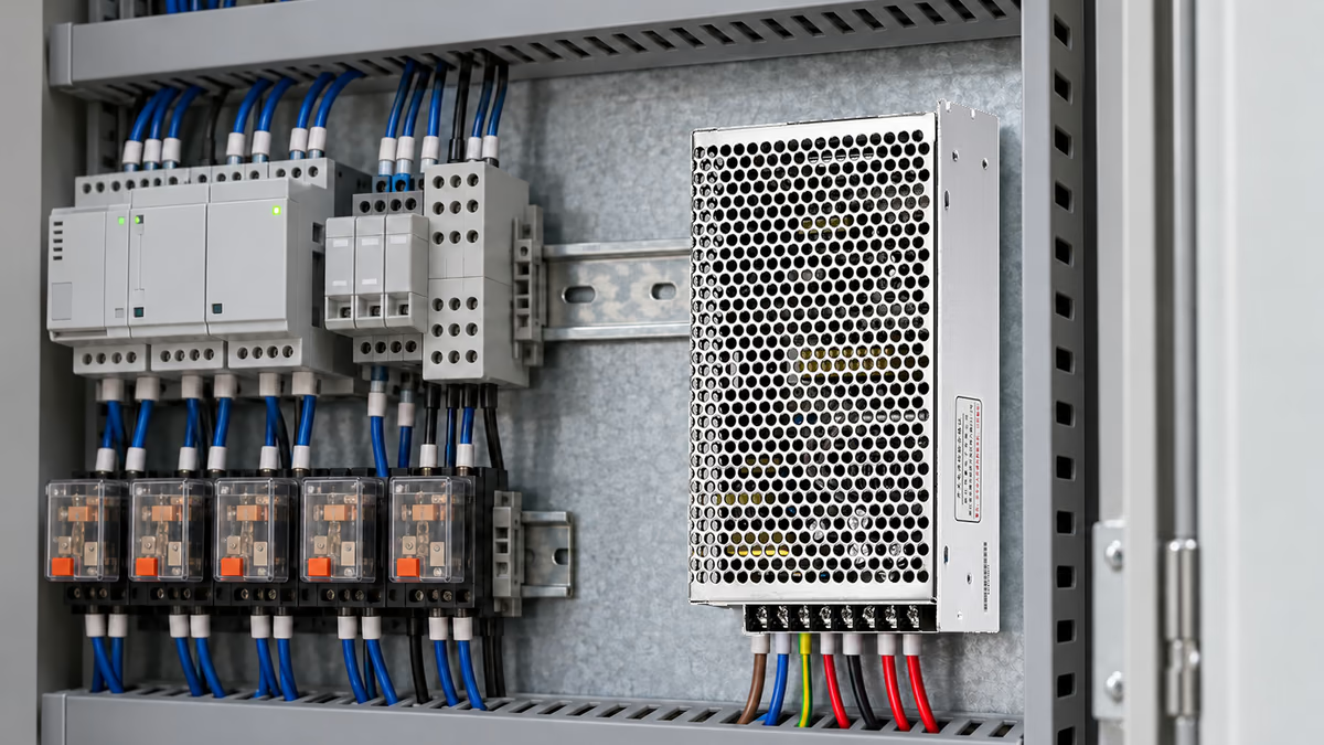
A shared return contact can carry the sum of several positive-rail branch currents. Checking each outgoing wire separately can therefore miss the highest current in a dual-output harness. The decision is whether the chosen return arrangement meets the equipment's electrical and thermal limits throughout its operating cycle.
This matters when a controller uses one voltage for logic and another for an actuator. A connector that appears lightly loaded on each positive pin may concentrate both return currents in one common contact. The result depends on the actual wiring, simultaneous demand, contact resistance and cooling conditions.
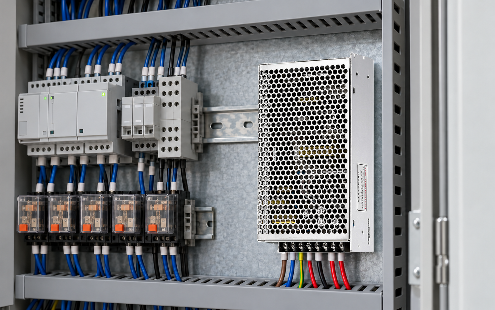
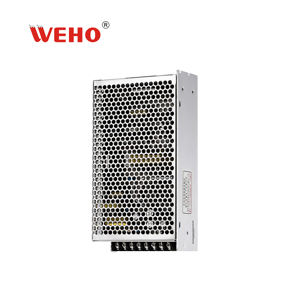
Ο D-120 dual-output product reference provides a relevant two-output example. Its published drawing identifies a common output reference. This article examines the downstream harness; it does not assign an additional terminal rating or prescribe combining conductors at a screw.
How do you calculate the shared-contact loss?
Use the current through the contact being assessed, rather than adding output powers and dividing by one arbitrarily selected rail voltage. Trace both outgoing and return paths first. Two branches only contribute to the same contact when the physical connection makes them share that segment.
Standard Engineering Sizing Example
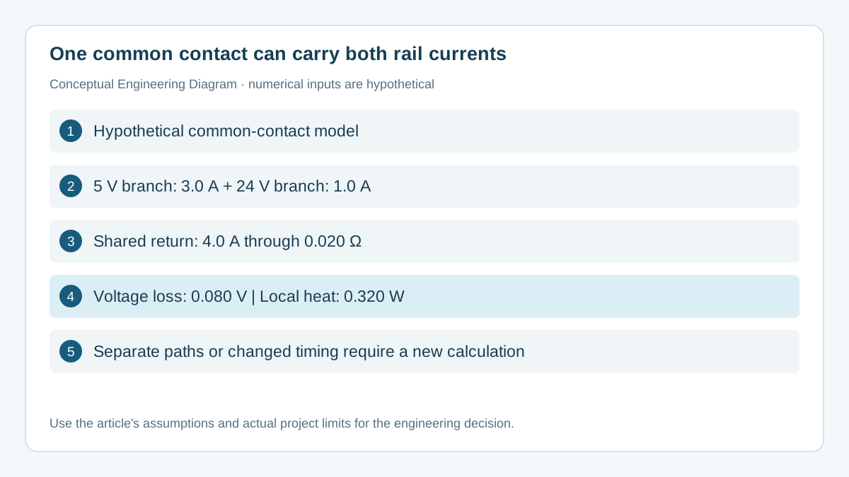
Assume a hypothetical 5 V logic branch draws 3.0 A and a 24 V actuator branch draws 1.0 A at the same time. Both return through one downstream connector contact. Assume the resistance of that contact and its defined termination region is 0.020 Ω at the condition being evaluated.
The positive-rail powers are 5 V × 3.0 A = 15 W and 24 V × 1.0 A = 24 W. Total delivered branch power is 39 W. This output total does not determine the current through the common return: the two currents sum to 4.0 A in the assumed shared segment.
The contact voltage loss is ΔV = I × R = 4.0 A × 0.020 Ω = 0.080 V. Its localized dissipation is P = I²R = 4.0² × 0.020 = 0.320 W. These are hypothetical calculations, not measured D-120 temperatures or approved contact limits.
For comparison, 3.0 A through the same assumed resistance produces 0.180 W. The extra 1.0 A increases the loss by 0.140 W, or about 78% relative to 0.180 W. The heating grows with current squared; it does not increase merely in proportion to branch count.
A temperature rise cannot be calculated from 0.320 W alone. It also depends on the contact construction, thermal path, neighboring loaded contacts, enclosure temperature and airflow. Obtain the connector's applicable loading information and verify the assembled condition rather than converting watts into an invented temperature.
Which operating states belong in the return-current matrix?
Include the combinations the equipment can actually produce. A separate maximum for each branch is insufficient when software, maintenance or abnormal operation can energize them together. Conversely, do not add mutually exclusive peaks without checking the enforced operating logic.
| Hypothetical state | 5 V branch | 24 V branch | Shared return | Loss at 0.020 Ω |
|---|---|---|---|---|
| Logic only | 3.0 A | 0 A | 3.0 A | 0.180 W |
| Both active | 3.0 A | 1.0 A | 4.0 A | 0.320 W |
| Reduced logic | 1.5 A | 1.0 A | 2.5 A | 0.125 W |
If an actuator pulse lasts only briefly, preserve its duration and repetition rate. An average current can help describe a thermal cycle, but the electrical drop during the pulse still follows the instantaneous current. Keep pulse-voltage acceptance and longer-term contact heating as separate checks.
A current sum also needs a direction convention. The example assumes both positive rails supply loads returning to common. A circuit involving negative rails, regenerative loads or other power sources requires a signed current-path analysis. Do not extend this simple addition rule to a different topology without redrawing the paths.
What should you measure before changing the harness?
Measure the voltage across the defined shared segment and the current through it under the relevant load state. This distinguishes a local contact problem from a supply adjustment issue. The reference points should enclose the contact being investigated, rather than an arbitrary length of cable plus several unrelated joints.
- Identify the connector part, contact position, wire termination and exact path in the current assembly drawing. Record all branches that share it.
- Establish the required operating states and permitted combination logic. Record both steady demand and repeated pulses.
- Use an appropriate measurement method to record segment voltage and current together. Keep instrument burden, lead placement and resolution in the measurement record.
- Observe temperature at defined locations after the agreed stabilization criterion is met. Record nearby ambient temperature and adjacent loaded contacts.
- Compare the assembled result with applicable connector, conductor and equipment limits. Investigate discoloration, damaged crimps or inconsistent readings before accepting a revised configuration.
For a small resistance, dividing a very small voltage by current can amplify measurement error. Record uncertainty and repeatability, and use the method specified for the connector or quality investigation. A continuity beep does not establish that a contact will remain acceptable under its operating load.
Disconnect and isolate the relevant energy sources before changing conductors or contacts. Energized measurements belong to qualified personnel using the equipment's approved procedure. This article does not prescribe a generic tightening torque, wire size or permission to place two wires in a terminal.
Which changes require a new return-path review?
Review the common segment after a branch-load increase, connector change, wire-gauge change or altered duty cycle. A firmware update can also change coincidence: two loads that previously ran separately may begin operating together. A supplier substitution affecting contact plating or crimp compatibility can change the evidence required even when the pinout remains unchanged.
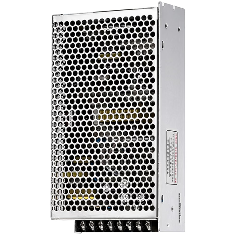
Use the D-120 output and common-reference documentation to identify the supply-side interfaces, then use the harness documentation for the downstream path. Common-reference availability does not grant unlimited current to every connector or make multiple return wires share equally.
Where separate return paths are proposed, review their complete routing and the receiver reference arrangement. Adding a second conductor is not automatically an equal-sharing solution. Contact resistance, wire resistance and connection geometry affect division, and the failure of one path may move the full current into the remaining one.
Keep one controlled record linking the branch schedule, connector arrangement, measured segment, acceptance limits and accepted assembly revision. That record makes a later thermal complaint easier to assess than a photograph showing that the power supply itself is below its nominal output rating.
What should an OEM send WEHO for the next review?
Send the required output combination, simultaneous branch currents, duty cycle, common-return drawing and observed operating conditions when discussing the D-120 dual-output supply interface. Include the downstream connector's applicable limits and any measured contact drop. Ask for the documentation matching the proposed supply version before freezing the BOM.
Engineering FAQ
Can I add the two positive-rail currents for every dual-output supply?
Add them only for a segment through which both currents flow in the same direction at the same time. Separate isolated outputs, different return routing or negative-rail loads need a different path analysis. The physical harness determines the shared-contact current.
Does a low total wattage prove that the return connector is adequate?
No. Output wattage and local contact current are different constraints. A low-voltage branch can carry substantial current, and a shared return can collect several branches. Check the supply budget and the assembled connection separately.
Is 0.020 Ω an acceptable contact resistance?
Not by itself. It is an assumed value used to show the calculation. Acceptance depends on the connector specification, measurement method, operating current, environment and equipment criteria. Do not copy this number as a production limit.
Will a larger power supply solve a hot common contact?
A larger supply does not remove the contact's current or resistance. Investigate the connection and load paths first. Increasing available fault energy can create additional coordination requirements, so a higher output rating is not a default repair.
Can protective earth carry the normal return current instead?
Protective earth is not a substitute for a designed load-return conductor. Keep protective bonding and operational return functions distinct in the equipment design. Any intentional reference bond must follow the applicable installation and safety documentation.