



Key Engineering Takeaways
- Charger output current and current entering the battery can differ substantially.
- A shared load can mask a battery-current termination threshold when sensing includes both branches.
- Separate system and battery paths must be verified from the exact charger documentation.
- Size recharge capacity after accounting for the operating load and the permitted charge profile.
Start with the current path, not the charging indicator
A charger can supply an operating load while the battery receives little current or even discharges. A “charging” indication alone does not establish the battery’s net current, recharge rate, or completion state. OEM equipment that stays powered during charging needs a defined current path and a documented charging decision.
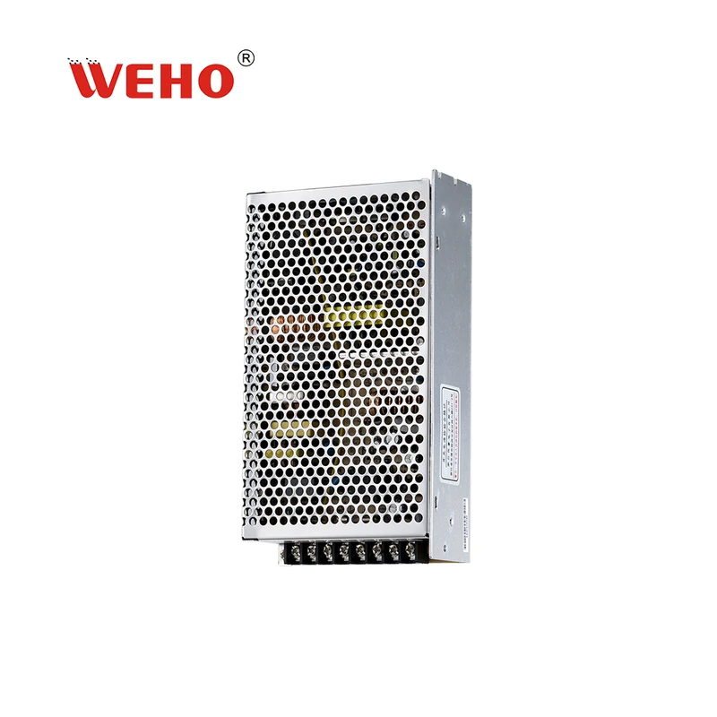
El WEHO AD-155 supply with charger output is a relevant product family for reviewing this interface. Its product page describes a primary output and a smaller-current charging output. Specify the exact variant and obtain its connection and charging documents before assigning loads or battery types. A family photograph does not identify every suffix or reveal the internal sensing logic.
The method below is not an AD-155 charging-algorithm description. WEHO’s industrial battery charger selection article addresses the earlier chemistry and charger-selection task. This article focuses on current measurement and charging decisions after an operating load is introduced.
Distinguish three currents at a shared DC node
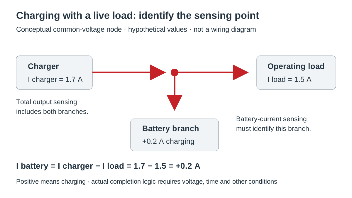
For a simple common-voltage node, define charger current entering the node as Icharger, current leaving for the equipment as Iload, and battery current as Ibattery, positive when charging. Neglect other branches and measurement error in the initial model:
Ibattery = Icharger − Iload.
A charger-side current reading includes both the battery and load branches in this topology. A sensor placed only in the battery branch measures a different quantity. Draw the sensing point and current direction on the system diagram; two instruments showing different values can both be correct when they observe different branches.
This current equation must be applied at the same electrical node. If a converter separates a system rail from the battery rail, currents cannot be subtracted directly across different voltages. Account for conversion efficiency and auxiliary consumption, or measure each relevant branch at its own location.
TI’s power-path explanation identifies the shared-node limitation: a charger sensing total output current cannot inherently distinguish system demand from battery charge current. A suitable power-path architecture can separate those functions. That architectural principle does not prove that a particular industrial charger implements it.
Quantify what remains for the battery
Hypothetical operating-load budget
Assume a charger can deliver 10.0 A at the common DC node under the actual input and temperature conditions. The equipment takes 6.0 A continuously. Assume the battery is allowed to accept the remaining current, the charger is in a current-limited charging stage, and no other branch consumes current. These are hypothetical conditions, not WEHO ratings or a battery recommendation.
The available battery current is 10.0 − 6.0 = 4.0 A. Selecting the charger as though its entire 10.0 A replenishes the battery would overstate the available current by 6.0 A. If the operating load rises to 10.8 A and the battery supports the deficit, battery current becomes 10.0 − 10.8 = −0.8 A: the battery is discharging while the external source remains present.
Swipe horizontally on a small screen, or open the full-size diagram.
| Hypothetical state | Charger current | Load current | Net battery current |
|---|---|---|---|
| Normal operating load | 10.0 A | 6.0 A | +4.0 A charging |
| Load exceeds source capability | 10.0 A | 10.8 A | −0.8 A discharging |
| Near-end charging with live load | 1.7 A | 1.5 A | +0.2 A charging |
The last row illustrates a different operating stage. Assume a hypothetical charging controller considers battery current below 0.4 A when evaluating a completion condition. The actual 0.2 A battery current is below that threshold, but the total 1.7 A charger output is not. A total-current sensor would not establish that the battery-current criterion had been met.
This is not a complete termination rule. Real algorithms can also require voltage, time, temperature, and operating-state conditions, and some systems maintain a permitted float stage rather than ending output altogether. Obtain the exact battery and charger requirements before deciding what “complete” means.
Victron’s IP22 charger operation manual documents this practical issue for its own current-sensing implementation: connected loads can make a tail-current condition difficult or impossible to meet using charger output current. Its solution and settings apply to that product; they are evidence of the measurement problem, not instructions for configuring an AD-155.
Account for cycling loads
Average load current can hide alternating charge and discharge. In another hypothetical common-node case, a source delivers 5.0 A while a load alternates between 6.0 A for 30 seconds and 2.0 A for 30 seconds. Assume the battery and power paths permit both intervals and ignore losses for the calculation.
Battery current is −1.0 A during the high-load interval and +3.0 A during the low-load interval. Over one minute, the net charge change is [−1.0 × 30 + 3.0 × 30] ÷ 3,600 = 0.0167 Ah, equivalent to an average +1.0 A. That arithmetic does not prove acceptable battery cycling, temperature, or equipment voltage during the peaks.
Record peaks and durations as well as averages. A large nameplate battery capacity cannot correct an unsuitable current limit, voltage drop, transfer behavior, or charging algorithm. Recharge-time estimates must also include the battery’s acceptance behavior and the later charging stages rather than dividing capacity by the charger nameplate current alone.
Choose an architecture using documented behavior
A shared charger/battery/load connection is only one arrangement. Dedicated system and battery paths may allow independent battery-current measurement and load priority, but those behaviors must be explicit. Microchip’s load-sharing application note AN1149 illustrates a specific implementation for its charge-management devices, showing why load sharing is a designed circuit function rather than a general property of a charger.
| Arrangement | Question to resolve | Evidence required | Suitable decision basis |
|---|---|---|---|
| Shared battery/load node | Does charging logic sense the combined current? | Current-sense location and algorithm description | Evaluate live-load effects on charging decisions. |
| Separate system and battery outputs | How are current limits and power allocated? | Exact output assignments and combined limits | Budget each branch and verify transfer behavior. |
| Managed power-path controller | When does the battery supplement the source? | Controller operating states and thresholds | Check startup, priority, charge reduction, and faults. |
| Load removed during charging | Is interruption permitted for this equipment? | Operating procedure and battery charge profile | Confirm the permitted maintenance use case. |
TI’s BQ24072 documentation provides an example of a named power-path charger family with separate system behavior. It is a single-cell IC product, not a substitute for an industrial charger. Use such examples to formulate questions, then verify the actual industrial product’s topology, voltage range, protections, and operating limits.
Two terminals labeled “output” and “battery” do not by themselves establish independent sensing, simultaneous full-current capability, or suitability for every battery chemistry. Check the current limits both individually and together. Confirm how temperature and input conditions affect the available system and charging power.
Verify charging with the real operating load
- Identify the battery and charger. Record battery chemistry, series count, capacity, permitted charge profile, charger variant, and document revision. Verify voltage, current, temperature, and protection requirements against the battery manufacturer’s instructions.
- Map branches and sensing points. Record charger, load, battery, and auxiliary paths with current directions. Verify whether each displayed or measured current represents total output or net battery flow.
- Measure the operating states. Record synchronized currents and voltages during startup, maximum normal load, load cycling, and the near-end charging stage. Check the measured branch balance, including instrument uncertainty and unmeasured auxiliary loads.
- Observe the charging decision. Record the actual transition conditions, status outputs, timers, and battery current. Verify these against the documented algorithm rather than treating a lamp or an output-current reading as proof of completion.
- Qualify source loss and recovery. Use a controlled test plan to record load voltage, transfer behavior, recharge response, and permitted battery-disconnect conditions. Verify against equipment limits and the battery protection requirements; use the specified protection and competent personnel.
The test plan should preserve the intended battery protection and charging controls. Do not bypass a battery management system to force a test result or increase a current limit to make a charging indicator change. A current measurement answers the current-flow question; it does not independently certify the entire charging system.
Define the product interface before ordering
Start from the AD-155 product and variant entry, then send WEHO your battery and load requirements. Include the exact battery specification, normal and peak load, desired operation during charging, ambient conditions, and required charging/backup behavior. Request the applicable variant documents and confirm how the proposed system is intended to operate.
Engineering FAQ
Can a battery discharge while its charger is connected?
Yes, if the load exceeds the source’s available contribution and the power path permits battery support. Measure net battery current and equipment voltage during the relevant load interval to establish what actually happens.
Is charger output current the same as battery charging current?
Not when the output also supplies an operating load at the same node. Net battery current is the charger contribution minus the load and any other branch currents, with direction defined consistently.
Does a connected load always prevent charge termination?
No. The effect depends on the sensing location and the charging algorithm. A system that measures the battery branch can distinguish battery acceptance from system demand; verify that capability in the exact product documentation.
Can I infer the recharge time from the charger’s rated current?
No. Recharge time depends on the current actually entering the battery and its permitted charging stages. Account for the live load, source limits, charging losses, and the battery manufacturer’s completion conditions.



