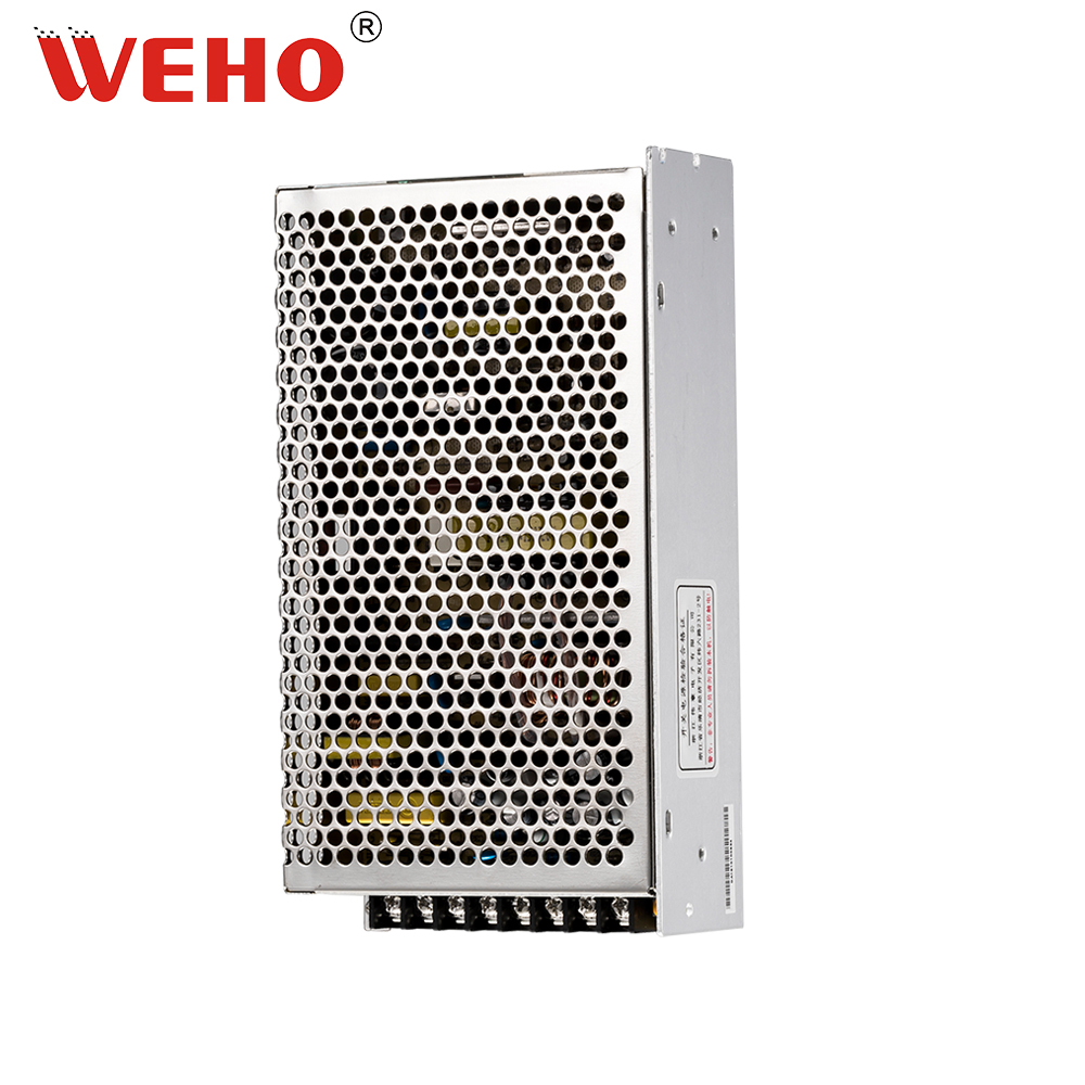
A differential ADC input must accept both the voltage difference being measured and the voltage of each input relative to its reference. Passing the differential range alone does not establish that a multi-rail monitoring interface will work.
- Calculate common-mode voltage as well as differential voltage.
- Separate normal conversion limits from absolute maximum ratings.
- Review every startup and powered-off state before connecting rail monitors.
Why can a small differential voltage still overload an input?
Both ADC inputs can sit outside their permitted operating range even when the voltage between them is small. A differential converter does not automatically provide isolation or unlimited input common-mode capability. Its datasheet defines the usable input conditions and any required front-end circuit.
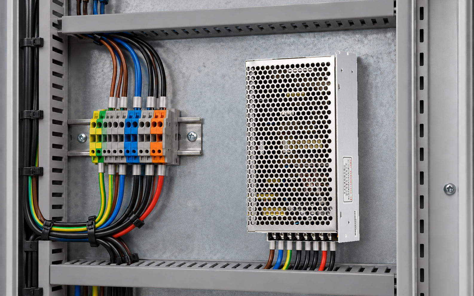
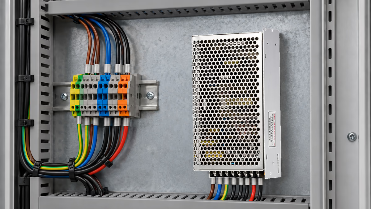
For an OEM monitoring a Q-120 multi-output supply assembly, each rail needs a defined sensing interface. The family image establishes the relevant product context, not the output combination or ADC compatibility of every ordered variant.
A common error is choosing a converter for a ±100 mV differential range and then placing it across a shunt several volts above the converter reference. The shunt drop may fit the differential range while the individual pins exceed their conversion or absolute limits.
This is a different question from channel switching and settling. A perfectly settled input can still be outside its allowed common-mode range. Resolve electrical compatibility before optimizing the sampling sequence; a longer acquisition delay cannot repair an input-range violation.
How are differential and common-mode voltage calculated?
Use Vdiff = V+ − V− and VCM = (V+ + V−) ÷ 2, with all node voltages referenced consistently. Then compare each actual pin voltage and the calculated difference with the selected ADC or amplifier's applicable limits.
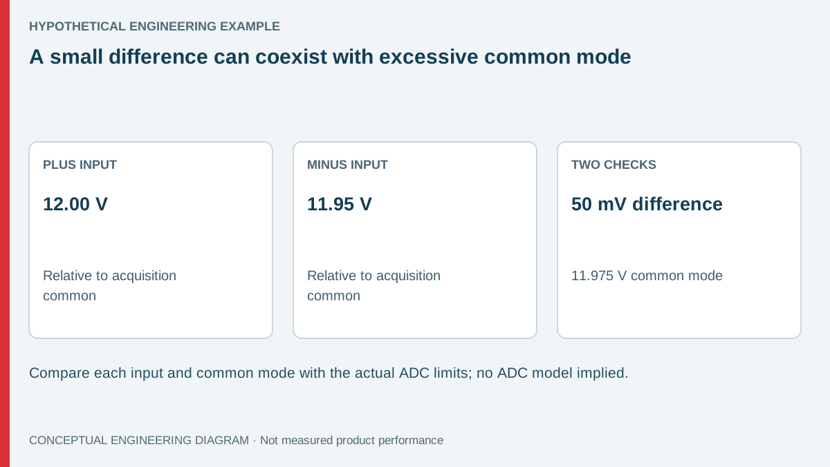
In a hypothetical high-side shunt measurement, V+ is 12.00 V and V− is 11.95 V relative to the acquisition reference. The difference is only 0.050 V, while common mode is 11.975 V. A small differential range says nothing about permission to place those pins near 12 V.
Suppose a proposed input stage has a hypothetical valid common-mode interval of 0.2–3.0 V and a ±0.100 V differential interval. The example passes the differential check and fails the common-mode check. Those limits illustrate the decision; they are not specifications for a real ADC or a Q-120 output.
An appropriate high-side measurement front end may translate the signal into a usable range, but its selection requires the actual rail, fault and power-sequence conditions. Do not add identical dividers to both inputs and assume that every accuracy, common-mode and transient issue has been resolved.
| Hypothetical item | Calculated or assumed value | Decision | Next action |
|---|---|---|---|
| Differential voltage | +0.050 V | Inside the example ±0.100 V interval | Still check all other limits |
| Common-mode voltage | 11.975 V | Outside the example 0.2–3.0 V interval | Select a suitable interface |
| Individual input voltages | 12.00 V and 11.95 V | Require pin-by-pin review | Check normal and absolute limits |
| Unpowered acquisition stage | Not established by the arithmetic | Separate unresolved state | Review injection and sequencing conditions |
Which datasheet sections need separate checks?
Start with recommended operating conditions and the input range under the intended supply voltage, gain and reference configuration. Some converters' common-mode limits depend on gain or internal architecture. A headline input span may not describe every operating mode.
Then review absolute maximum ratings. These generally describe stress boundaries, not a guaranteed accurate conversion range. An input that avoids immediate damage can still produce an invalid reading. Do not report “within absolute maximum” as evidence that a monitoring channel meets its measurement requirement.
Input protection and injection current also matter when the monitor is unpowered or a rail starts first. A divider or series resistor may limit current, but component selection must follow the actual front-end requirements. Do not assume an internal clamp is intended to carry a continuous fault current.
Use primary ADC and amplifier documentation for the selected parts. Analog Devices' ADC testing note explains input-range terminology, but the exact device datasheet remains necessary. A general explanation cannot approve a particular front end, isolation barrier or protection network.
How should a multi-rail state matrix be built?
List every rail, the acquisition-stage supply and any external connection that can establish a reference. Include normal operation, startup, shutdown and partial-power states. A multi-output supply and the monitoring electronics may not become valid at exactly the same instant.
- Define which two nodes each channel measures and their reference relationship.
- Calculate normal differential, common-mode and individual pin voltages.
- Repeat for rail tolerances and the intended adjustment range.
- Review states where a rail remains present but the ADC supply is absent.
- Verify the chosen interface against applicable limits and document the result.
Do not turn the matrix into an unsupported claim about the supply's sequencing. If sequencing data is required, obtain it or define an appropriate test. The matrix identifies which interface states must be handled; it does not predict their duration without evidence.
A failure-state review should also consider an open sense connection or an incorrectly connected reference where relevant to the project. The possible voltage may differ from the normal calculated value. Use the actual protection design and component documentation rather than assuming a disconnected input always reads zero.
What must be validated after the range check passes?
Range compatibility is necessary but does not prove measurement accuracy. Divider ratio, reference accuracy, amplifier offset, leakage, input loading and calibration can affect the result. Dynamic acquisition time remains relevant after the electrical interface is valid.
For a hypothetical divider, two nominally equal resistor ratios can still produce a differential error when their actual ratios differ. Common-mode rejection in the complete circuit includes those external components, not just an amplifier's published figure. Choose tolerances and temperature behavior for the required uncertainty budget.
El Q-120 product information helps identify the supply family for the project. Use the ordered output combination and its applicable documentation when populating the state matrix. The supply does not become ADC-compatible merely because its rails are described as low voltage.
Validate the current sensing assembly as built. Cable reference paths, connector states and protection components can alter pin conditions from those in the schematic. Capture the actual front-end input and output behavior under representative states without exposing the ADC to conditions outside its approved method.
Treat a disabled channel and a physically disconnected channel as different states. A multiplexer can still expose an unselected input pin to a rail, and input protection can remain relevant while no conversion is requested. The selected component documentation determines those conditions.
The interface review should preserve the reference path through connectors and cable shields where relevant. A schematic label called common does not establish a zero-impedance reference in the assembled equipment. Investigate actual pin voltages under the defined states instead of approving the interface solely from ideal net names.
Prepare a Q-120 monitoring-interface review
Send WEHO the exact output combination, required monitoring quantities and a rail-state table. Include the selected acquisition-interface documentation for the engineer responsible for that design. Separating the supply's defined outputs from the monitor's electrical limits makes a supplier discussion more precise and avoids treating an invalid reading as evidence of a rail fault.
Frequently asked questions
Does differential input mean galvanically isolated input?
No. Differential describes how a signal is measured; isolation describes an electrical barrier and its specified properties. Verify both independently when the application requires them.
Can software subtraction solve a common-mode problem?
No. Software operates on acquired results and cannot make an electrically invalid input valid. The hardware interface must first remain within its applicable operating and stress limits.
Should absolute maximum ratings be used as the conversion range?
No. Use the conditions under which conversion performance is specified. Absolute maximum ratings are separate stress limits and do not guarantee a useful or accurate result.
Is one normal-operation calculation enough?
No. Startup, shutdown and partial-power conditions can expose inputs to different voltages and reference relationships. Review those states before approving the interface and then validate the relevant behavior.