Extend an LED driver’s output cable only after checking the complete driver, cable, controller, and LED combination. A satisfactory voltage-drop calculation does not establish acceptable startup, dimming, electromagnetic compatibility, or permission to switch the secondary circuit. For a constant-current load, include the cable drop in the driver’s required output-voltage window. For a constant-voltage load, check the voltage delivered at the module. Then verify the model’s installation restrictions and test the proposed assembly.

فهرست مطالب
An LED driver extension cable changes the electrical path between a remote LED driver and the light engine. This guide helps luminaire and signage OEMs decide whether that layout can proceed to startup, harness, and EMC validation. It does not assign a universal maximum cable length to WEHO XLG or HLG products.
Define the cable being extended
Draw the actual power path before requesting a maximum distance. Distinguish the AC supply lead, the driver’s DC output lead, any cable after a PWM controller, and the separate dimming-control pair. A control-bus distance is not an output-power cable rating. Record one-way route length and calculate resistance using the complete outgoing and return path.
Also identify whether the quoted distance includes the driver’s factory lead, extension joints, connectors, and links between modules. A chain with a short driver-to-first-module cable can still have a long secondary path. The approved wiring definition should follow the actual model documentation rather than a convenient length measured on the installation drawing.
| Path | Electrical question | Additional check |
|---|---|---|
| Driver to CV module | Minimum voltage at the module | Connector drop and module input current |
| Driver to CC string | Required driver voltage at set current | Minimum and maximum operating window |
| Controller to LED module | Voltage drop during current pulses | Controller cable and load restrictions |
| Dimming-control pair | Interface signal conditions | Separate protocol and wiring limits |
Check the operating window
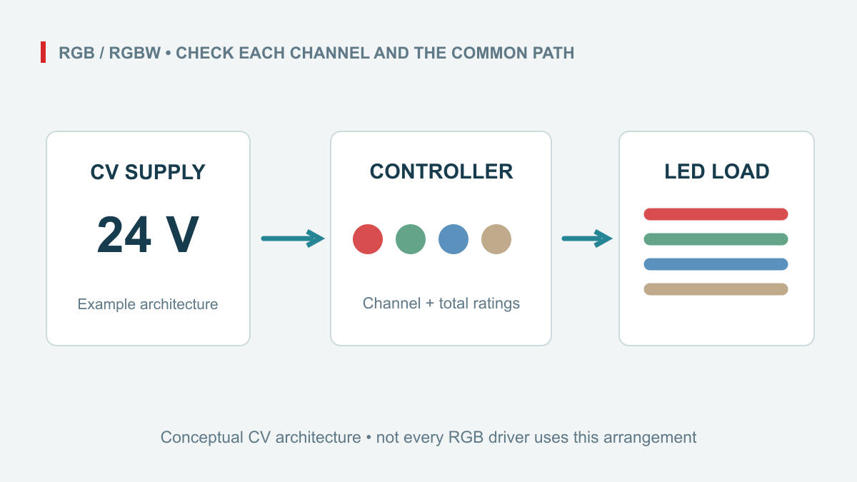
For a constant-voltage load, calculate voltage at the remote module using the DC cable and load-voltage budget. A constant-current string requires the different window check below.
For a CV system, subtract the worst credible output-path drop from the driver’s minimum available voltage and compare the result with the module’s permitted input range. Increasing the output adjustment to compensate can expose a nearby branch or a lightly loaded module to excess voltage. Evaluate every branch, not only the farthest point.
For a CC system, the driver must develop the LED string’s forward voltage plus the cable and connection drop at the set current. Use a complete constant-current voltage-window screen for the LED string itself. Use LED forward-voltage limits across temperature, production variation, and dimming conditions as applicable. Check the lower window as well as the upper limit; a higher-wattage driver is not automatically compatible with a low-voltage string.
MEAN WELL’s application FAQ identifies both insufficient LED voltage and changed EMC behavior as concerns when extending DC cables. That general warning supports a system review, not a transferable WEHO cable-length rating. See MEAN WELL LED application FAQ, question 13.
For a specific 24 V source review, use HLG-200 product details: HLG-200-24 variant and the HLG-200 datasheet (PDF): HLG-200-24 column as document starting points. Confirm the actual output mode, startup and capacitive-load behavior, and permitted harness arrangement with the model’s applicable instructions. The pictured source is not selected for the constant-current example below, and its documents do not establish a universal cable-length rating.
Calculate a constant-current example
Hypothetical design, not a WEHO specification: a 700 mA string needs 39.8–43.2 V over the defined operating conditions. A candidate driver has an assumed 36.0–44.0 V constant-current window at that current. The proposed extension has 1.60 Ω total loop resistance at the chosen design temperature, including connections.
Cable drop = 0.700 A × 1.60 Ω = 1.12 V. At the highest assumed string voltage, required driver voltage = 43.2 V + 1.12 V = 44.32 V. That exceeds the assumed upper window by 0.32 V, so this combination fails the steady-state voltage screen.
| Quantity | Original extension | Lower-resistance option |
|---|---|---|
| Total hot loop resistance | 1.60 Ω | 0.80 Ω |
| Drop at 700 mA | 1.12 V | 0.56 V |
| Driver voltage for 43.2 V string | 44.32 V | 43.76 V |
| Headroom below assumed 44.0 V limit | −0.32 V | 0.24 V |
The second option clears this arithmetic screen, but 0.24 V is only the remaining allowance under these assumptions. It is not proof of startup performance or a recommended design margin. At the minimum string voltage, it requires 39.8 V + 0.56 V = 40.36 V, also within the assumed window. Actual tolerances and transient behavior still need evaluation.

Assess capacitance, routing, and EMC
If dimming/control conductors share the route, retain the LED driver dimming-interface review as a separate check. For an outdoor sign, also qualify the complete IP67 supply installation, including cable entries and connections.
A cable also adds capacitance and inductance. Line-to-line capacitance affects the differential output path; capacitance to a shield or metalwork affects common-mode current paths. These are not interchangeable values. Include the LED module and any controller input capacitance when reviewing the driver’s permitted capacitive load.
For a documented example, see the capacitive-load entry in the referenced external LED-driver datasheet. This demonstrates why capacitance belongs in a model-specific review; its numerical limit must not be applied to another manufacturer or family.
Keep outgoing and return conductors arranged as instructed, document separation from mains wiring, and preserve the intended bonding and shielding arrangement. A ferrite, shield, or added output capacitor changes the circuit. Do not treat any of them as an automatic cure or copy a filter from a different installation. Test the resulting assembly against the requirements that actually apply to the finished equipment.
Review switching and service behavior
A removable connector can unintentionally become a secondary-side switch. Ask what happens when it is disconnected, reconnected, or momentarily intermittent while the driver is energized. Residual output charge and the driver’s recovery behavior can matter even when the steady-state string voltage is acceptable.
Restrictions are specific: the referenced LED-driver datasheet, installation section prohibits secondary switching and hot plug-in for the covered products. That is an example of a documented restriction, not evidence that every driver has identical behavior. Use the selected model’s service and discharge instructions.
Validate the assembled harness
Use the production cable, connectors, module quantity, and controller. A short bench lead is not a substitute for a coiled or routed production harness. Cover the worst credible LED voltage, cable temperature, input voltage, and dimming states. Change one variable at a time when diagnosing flicker or intermittent startup.
| Check | Record | Decision |
|---|---|---|
| Steady operation | Driver and LED-end voltages, current, temperatures | Within documented operating limits |
| Startup and dimming | Waveforms and observed behavior at required states | No unacceptable overshoot, dropout, or flicker |
| Harness construction | Wire type, route, connectors, shielding, revision | Matches the reviewed configuration |
| EMC verification | Assembly configuration and applicable test results | Requirements satisfied for the finished system |
Request model-specific cable guidance
Contact WEHO about a remote-driver layout through the contact form with the LED load specification, proposed one-way cable length and conductor size, any controller or switching arrangement, and installation temperature. Mark unknown details as unknown; an initial inquiry does not require a finished harness design.