



A voltage sag is a temporary reduction in AC RMS voltage; IEC immunity documents use the term voltage dip for this disturbance. For an OEM, it becomes a power-supply problem when a controller resets, a contactor drops out, communications fail, or the machine restarts incorrectly. Qualify the input event and the required equipment recovery together. A nominal AC input range, a single hold-up-time figure, or a successful restart after unplugging the equipment does not establish that result.
Start with a written decision: must the equipment continue operating through the event, enter a defined stopped state, or recover through a controlled restart? Then measure the AC event, the critical DC rails, and the relevant equipment functions on the same time base.
Article sections
Define the event at the equipment input
A useful sag description gives the initial voltage, residual voltage, duration, supply frequency, and recovery profile. Record the event initiation angle where required by the adopted test plan. State whether a percentage describes the voltage remaining or the voltage reduction. Those two conventions can describe very different events with the same number.
For three-phase equipment, identify the affected phases and their relationship. For a single-phase power-supply evaluation, retain the input source and any upstream transformer, contactor, filter, or long cable that forms part of the proposed equipment configuration. A record taken elsewhere in the building may not describe what reached the power-supply terminals.
| Field | What to record | Why it changes the interpretation |
|---|---|---|
| Initial and residual voltage | RMS volts and the residual percentage, with its reference | Separates a shallow dip from a near interruption |
| Duration and frequency | Milliseconds; cycles only with frequency stated | The same cycle count gives different times at 50 and 60 Hz |
| Transition and recovery | Agreed source profile, event timing and repetition | A clean recovery and an unstable repeated disturbance are different cases |
| Equipment state | Load, enabled functions, temperature and cable arrangement | A lightly loaded bench sample does not represent the worst machine state |
| Required response | Continuous function, defined stop, or controlled restart | Makes a pass/fail decision possible before the test |
Worked example: convert percentages and cycles before comparing
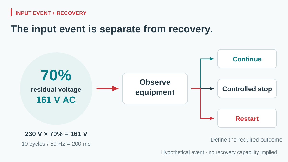
Assume a project defines an input event at 230 V AC RMS, 70% residual voltage, lasting 10 cycles at 50 Hz. These are hypothetical project inputs, not prescribed test levels or a WEHO capability claim.
Residual voltage = 230 × 0.70 = 161 V RMS
Duration = 10 ÷ 50 = 0.20 s = 200 ms
View full diagram ↗
The voltage reduction in that description is 30%. If someone instead writes “70% reduction,” the residual voltage is 69 V RMS. At 60 Hz, ten cycles last about 166.7 ms, so the original 200 ms event cannot be reproduced merely by keeping the cycle count unchanged.
This calculation defines the stimulus; it predicts neither the DC output minimum nor the equipment’s recovery. Load, stored energy, input circuitry and downstream conversion determine what follows. Do not compare a 200 ms partial-voltage event directly with a datasheet hold-up number taken at another input, output load or measurement threshold.
Observe the power chain and the application together
An AC disturbance can reach a controller through several stages: the AC-DC supply, cable distribution, a local DC-DC converter, and the processor’s supervised rail. Each stage has its own operating limits and recovery behavior. A cabinet supply may have recovered while an attached controller is still booting or awaiting a manual command.
When specifying brownout protection, distinguish a reset decision from ride-through. A supervisor can assert reset when its monitored rail crosses a threshold; that does not supply missing energy or keep the application running. TI’s LM3710 documentation illustrates separate reset and early power-failure functions. Its device-specific thresholds are not settings for an industrial 24 V power supply.
Qualified test personnel should choose the measurement arrangement appropriate to the energized equipment. The useful deliverable is a synchronized record that shows the applied event, supply-terminal voltage, voltage at the critical load, and observable function. For the DC distribution part, the 24 V voltage-budget guide explains why supply-terminal voltage and load voltage need separate checks.
Use the NDR-240-24 specification to define the next test
For a nominal 24 V cabinet source, start a model-specific review with the WEHO NDR-240-24 product details and NDR-240 specification. The sheet lists 24 V, 0–10 A output and an 85–264 V AC operating input range. The example’s 161 V residual lies inside that stated AC range, but this alone does not show what the output or connected equipment will do during a 200 ms sag.
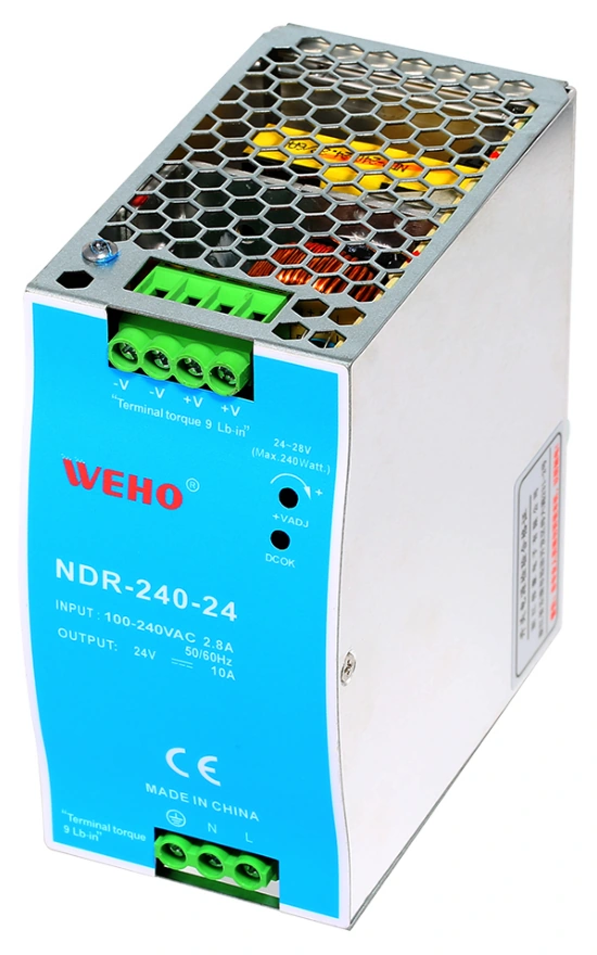
WEHO NDR-240-24 product photograph. Its stated AC input range is a screening reference, not evidence that the assembled equipment passed a voltage-sag test.
View original photograph ↗
| Document information | Required follow-up |
|---|---|
| 85–264 V AC input range | Verify the permitted load and operating conditions for the actual assembly |
| A combined setup, rise and hold-up timing row | Obtain individually defined timing values, input/load conditions and output thresholds |
| Identified 24 V supply | Record critical-load voltage and equipment function during the specified sag and recovery |
Use that review to agree a sample test, rather than converting an operating range or an ambiguously grouped timing entry into a ride-through promise. If the required continuity cannot be established, review the energy or backup architecture before releasing the equipment configuration.
Write recovery criteria that match the machine’s job
“Output comes back” is too weak for equipment qualification. Set a permitted recovery time, specify which functions may stop, and identify what a person or supervisory controller must do next. Where a project requires a particular controlled or protective state, its responsible engineering team must define that behavior; the power-supply article cannot establish a machine safety function.
| Project requirement | Observe during the sag | Observe after input recovery |
|---|---|---|
| Continuous operation | Critical rails and functions remain within their agreed limits | No hidden reset, data loss or uncommanded state change |
| Defined temporary stop | Equipment enters the agreed stopped state | Recovery follows the documented sequence and time limit |
| Restart requiring intervention | Loss of function is detected and reported as specified | Equipment waits for the required command instead of restarting unexpectedly |
Use these categories as planning language, not as a replacement for the applicable product standard’s performance criteria. Record an observed result separately from the acceptance decision. A power-on indicator, for example, is an observation; it is not proof that a controller retained its process state.
Choose the relevant test method and configuration
IEC 61000-4-11:2020 describes voltage-dip, short-interruption and voltage-variation immunity methods for qualifying low-voltage AC equipment within its stated scope. Its scope covers rated input current up to 16 A per phase on 50 or 60 Hz networks; it is not a general test specification for every AC or DC product. The applicable product requirements and the project agreement determine the relevant levels and criteria.
Agree the adopted edition and test plan with the laboratory. Ask its report to identify the exact equipment, supply model, firmware, input arrangement and load configuration. A component-level report can support the review, but the assembled equipment adds downstream loads, cables and restart logic that may need their own evaluation.
If continuity through a particular interruption requires stored energy or a backup path, treat that as a separate architecture decision. The hold-up time versus DC UPS guide covers that decision. Raising the nominal wattage alone is not a validated substitute for an energy and system-recovery requirement.
Send a reproducible requirement to the supply manufacturer
Ask WEHO to review your input-disturbance requirement with the event definition, critical load voltage limits, operating load, cabinet conditions and required recovery sequence. Identify any existing supply by its complete model and document revision. Request the applicable operating and recovery information and agree the sample evidence needed for the equipment test.
Keep the final record in three parts: the event actually applied, the system behavior observed, and the acceptance criterion used. That separation helps purchasing compare the same requirement across proposals and helps engineering distinguish a supply limitation from a downstream reset or distribution problem.




