



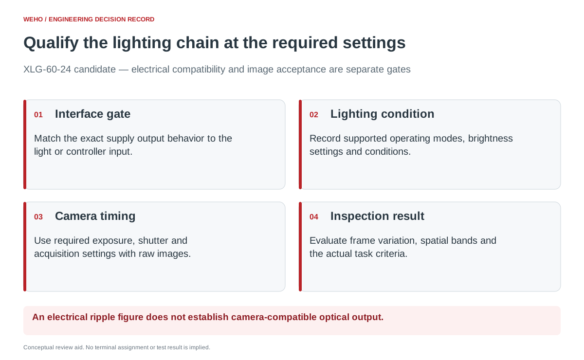
Qualify the LED supply, light or controller, and camera together at the exposure and acquisition settings the inspection actually needs. A light that looks steady to a person can still produce frame variation or bands in captured images. A supply’s wattage alone does not establish a camera-compatible lighting system.
This article helps an equipment builder create an image-acceptance matrix. The WEHO XLG-60-24 is a supply candidate for document review, not a claim of a tested machine-vision driver or a guaranteed banding-free result.
Confirm the lighting interface before comparing images
را WEHO XLG-60 product page lists the XLG-60-24 with a 24 V output entry, 2.5 A rated current and 60 W output power. Its table also lists a constant-current operating range. Confirm the exact output behavior and compatibility required by the proposed light before connecting it.
A light module requiring a regulated voltage input and an LED load requiring controlled current are different interfaces. Identify any intermediate controller and obtain the complete chain’s instructions. The public XLG-60 page does not establish a PWM dimming protocol, camera-trigger input, optical-flicker specification or strobe overdrive capability.
Keep those gaps visible in the selection record. If the light manufacturer’s interface cannot be matched to documented supply behavior, resolve that question before treating an image trial as product qualification.
Understand why the camera can reveal bands
Basler’s shutter documentation explains that a rolling shutter exposes successive sensor rows with a time offset. Different rows can therefore sample changing illumination at different times. Global-shutter acquisition changes the sampling relationship but does not, by itself, certify that every captured frame has equal brightness.
Basler’s Light Control documentation gives a specific example of PWM-controlled camera lighting causing brightness fluctuations or rolling-shutter stripes under certain short-exposure and brightness settings. That example supports checking the timing relationship. Its model-specific thresholds and settings must not be assigned to the XLG-60-24 or an unspecified camera.
Also keep electrical and optical quantities separate. A supply ripple entry describes an electrical measurement under its stated method. Image banding concerns how the light’s output is sampled by the camera. Neither figure can be substituted for the other without evidence from the actual lighting chain.
Build the acquisition matrix around the inspection requirement
Record the camera model, shutter mode, lens, firmware, image region and acquisition mode. Identify the light and controller, brightness command, supply revision and operating conditions. Fix the target and geometry so a change in framing is not mistaken for a lighting improvement.
| Matrix dimension | Conditions to include | Record for comparison |
|---|---|---|
| Exposure and acquisition | The shortest required exposure, nominal setting and required acquisition rates or trigger modes. | Actual camera settings and any documented timing limits. |
| Lighting command | Every brightness or continuous/strobe mode required by the application and supported by the equipment. | Exact controller setting and interface documentation. |
| Operating condition | Required startup and stabilized operation within the equipment ratings. | Condition, observation interval and lighting-chain configuration. |
| Inspection target | Uniform reference target and representative production features. | Raw image identifiers, regions used and inspection result. |
Select the required combinations before testing. A slower frame rate or longer exposure may remove a visible symptom while making the inspection miss moving parts. Accept only settings that still meet the actual task.
During controlled comparison, prevent automatic exposure or gain changes from silently changing the question. Record all relevant automatic processing and, where the approved test plan requires it, hold those settings constant. Retain the original files used for evaluation.
Judge frames and rows, then judge the inspection
Define what constitutes an unacceptable band or brightness change in the relevant image region. A uniform reference target can reveal spatial patterns, while representative parts show whether those patterns affect the intended measurement or detection. Keep saturated or otherwise unsuitable images out of a brightness comparison using criteria defined in advance.
One optional project metric is the normalized range of frame means: (largest region mean − smallest region mean) ÷ average region mean × 100%, using the same region and settings. This is a proposed comparison metric, not a standard flicker rating, an XLG-60 specification or a universal pass threshold.
Frame averages can hide a bright band beside a dark band. Add a row-profile comparison or another documented spatial criterion where banding matters. Have the vision team set tolerances from the inspection’s sensitivity, then evaluate the required defect-detection or measurement result separately.
A hypothetical exposure change is a clue, not an acceptance result
Suppose bands appear at a required short exposure and disappear after the exposure is lengthened. That observation would justify investigating illumination timing and camera sampling. It would not prove the supply is defective or establish that the longer setting is acceptable for the production speed.
The team would retain the two configurations, raw images and inspection outcomes, then compare one documented factor at a time within the equipment’s allowed operation. Possible changes to the light, controller, acquisition settings or supply need the same final matrix review. No actual XLG-60-24 test result is asserted in this example.
Avoid adding an undocumented strobe connection or overdriving the LED to hide the symptom. A camera’s available trigger output does not establish that an arbitrary power supply or light can receive it.
Approve a configuration and an operating window
The release should identify which hardware and settings passed the project’s image and inspection criteria, with traceable image files. List required modes that were not tested as open items. “Looks stable” is not an adequate record of exposure-dependent performance.
Revisit the qualification after a light-controller, camera firmware, brightness mode or supply substitution. Keep the approved operating window with the machine recipe so production adjustments remain within the settings that were actually evaluated.
Use the project record
Open the blank Machine-Vision Lighting — Acquisition Qualification Matrix to record your conditions, evidence and decisions. The worksheet contains no pre-approved result.
Review the XLG-60-24 against your light’s input requirements
Send WEHO the exact light or controller input specification, required operating mode, load and supply conditions. Request confirmation of the offered XLG-60-24 output behavior; use the vision team’s camera matrix to qualify the complete lighting chain.




