



A warmer current shunt can indicate a different current even when the actual current is unchanged. Calculate resistance change at the relevant element temperature before treating a drifting voltage-to-current conversion as evidence that a power-supply branch draws more current.
Key engineering takeaways
- Convert shunt voltage using an applicable resistance value.
- Include ambient temperature and operating self-heating separately.
- Keep shunt gain drift distinct from its circuit voltage burden.
- Verify thermal conditions before applying temperature correction.
What decision does a drifting current reading support?
An OEM test engineer may observe a branch-current indication increasing during a cabinet warm-up. The first useful question is whether the current changed, the measurement conversion changed, or both changed. A stable digital display later in the sequence does not answer which mechanism produced the earlier trend.
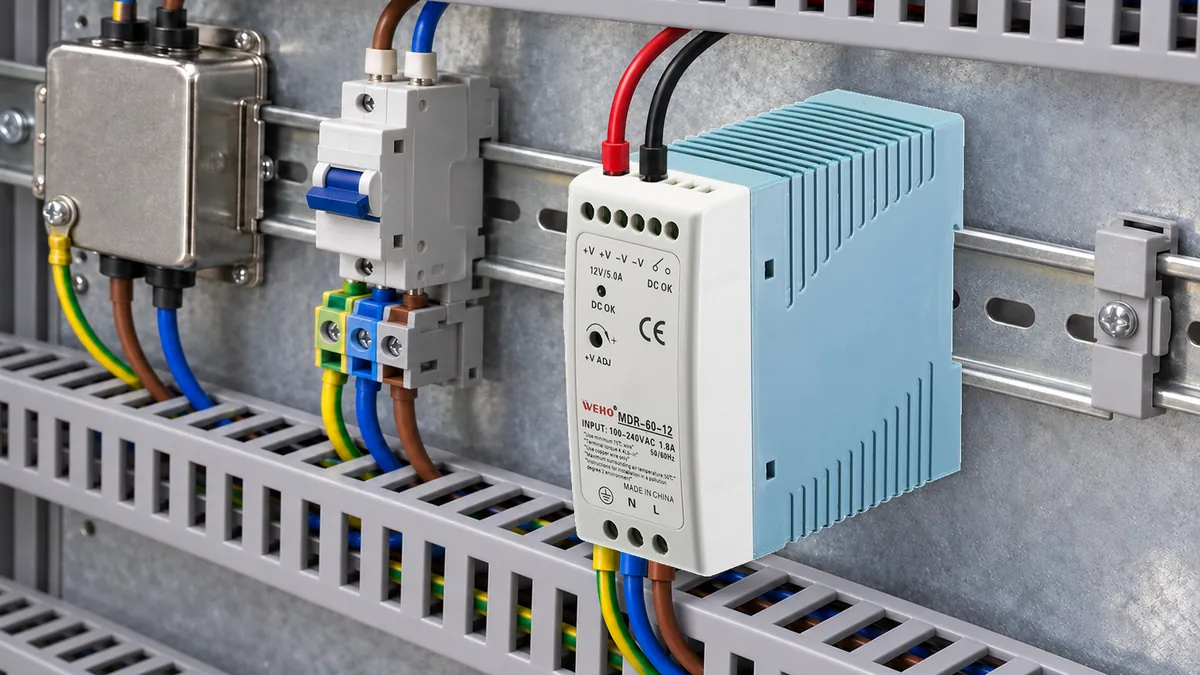
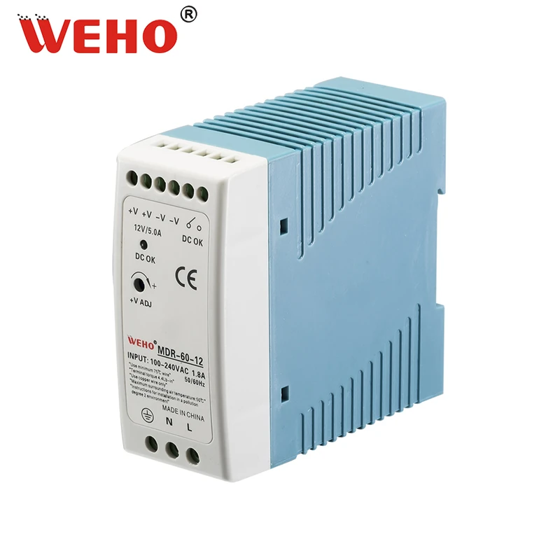
For an MDR-60-12 branch-current review, retain the actual supply identity, branch and receiver conditions. The product reference identifies the source under discussion. It does not specify a shunt, its temperature coefficient or an achieved test current.
The shunt belongs to the external measurement path. Its resistance, temperature and voltage-sense boundary need their own evidence. Do not assign an apparent percentage change to the MDR-60-12 merely because that model powers the branch being measured.
How does temperature change the conversion?
Current conversion commonly uses Iind = Vshunt/Rused. If the true resistance is Ractual while the software retains an earlier Rused, a constant actual current produces Iind = Iactual × Ractual/Rused. The resulting gain error is different from a fixed voltage offset in the amplifier or voltmeter.
Over a defined range where a linear approximation is applicable, write R(T) = Rref × [1 + α × (T − Tref)]. Express α in inverse degrees Celsius: 100 ppm/°C equals 0.000100/°C. Use the actual resistor's specified behavior rather than assuming every shunt has this coefficient, sign or linearity.
Vishay's current-sense application note distinguishes initial tolerance from temperature-related effects, including operating-power effects. A tightly grouped set of readings can still contain a consistent thermal error. Low scatter therefore does not establish that a nominal-resistance conversion remains accurate after the shunt warms.
A hypothetical 2 A measurement with a warming shunt
Assume a shunt is exactly 50.000 mΩ at 25°C and has an exactly linear positive coefficient of 100 ppm/°C over this example. Assume the actual current remains 2.000 A and the voltage measurement is ideal. These assumptions isolate the resistor effect; they are not a shunt specification, a WEHO measurement or a complete uncertainty budget.
At an assumed element temperature of 65°C, ΔT = 40°C. Resistance becomes 0.050000 × (1 + 0.000100 × 40) = 0.050200 Ω. The shunt voltage is 2.000 × 0.050200 = 0.100400 V, or 100.400 mV.
If software still divides by 0.050000 Ω, the indication becomes 2.008 A. The apparent increase is 8 mA, or 0.4%, despite the unchanged assumed current. Dividing by the correct 0.050200 Ω returns 2.000 A in this ideal model; real correction still requires valid temperature and resistance information.
| Assumed element temperature | Actual resistance | Voltage at actual 2 A | Indication using 50 mΩ |
|---|---|---|---|
| 25°C | 50.000 mΩ | 100.000 mV | 2.000 A |
| 45°C | 50.100 mΩ | 100.200 mV | 2.004 A |
| 65°C | 50.200 mΩ | 100.400 mV | 2.008 A |
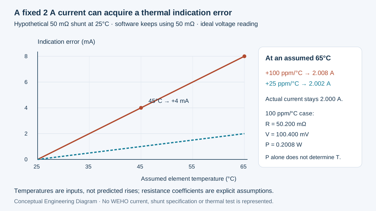
Swipe horizontally on a small screen, or open the full-size diagram.
At the last point, shunt dissipation is I²R = 2² × 0.050200 = 0.2008 W. That calculation does not predict a 65°C element temperature. The temperature is an explicit hypothetical input that can include cabinet heating and self-heating; the actual result depends on the component, mounting, conductors and heat-transfer conditions.
For comparison, an assumed 25 ppm/°C coefficient over the same 40°C difference would create a 0.1% resistance change. At the same actual current and nominal resistance, the indicated value would be 2.002 A. This sensitivity comparison does not recommend a particular shunt or establish that changing one coefficient meets the full measurement requirement.
Keep self-heating, burden and sense geometry separate
The voltage across the inserted shunt also subtracts from the voltage available elsewhere in its series path. That physical burden can change the actual load current, independently of the conversion error.
Four-terminal sensing can exclude certain connection-voltage drops from the measured resistance boundary. It does not make the resistor's element temperature irrelevant. Keep the force path, voltage-sense points, component resistance definition and thermal behavior identifiable in the test record.
TI's shunt-selection brief discusses resistance, dissipation, layout and temperature behavior as related selection variables. Apply the actual resistor's ratings and mounting conditions. Do not turn another manufacturer's application-specific design margin into a universal permissible fraction of a WEHO branch current.
| Contribution | Physical cause | Useful evidence | Do not substitute |
|---|---|---|---|
| Reference resistance error | Actual value differs from the conversion value | Applicable resistance characterization and uncertainty | Nominal marking alone |
| Thermal resistance change | Element temperature and operating-power effects | Documented coefficient/model and thermal state | Room-air temperature alone |
| Voltage burden | Inserted series voltage loss | Receiver voltage and current under the actual setup | A corrected software reading |
| Sense-path error | Unwanted conductor/contact voltage is included | Physical sense points and component instructions | A generic four-wire label |
Avoid counting the same thermal change twice. If a supplier's validated power-coefficient model already covers a self-heating contribution, an additional independently assumed temperature term may overlap it. Establish which effect each specification includes before combining numbers into an error allowance.
What temperature information can justify correction?
A room thermometer does not automatically report the resistive element's temperature. A package surface sensor can also differ from the element, especially during a transient. Define the measurement location, attachment, thermal lag and any model used to relate the observation to the relevant resistance temperature.
TI's worked current-sense design illustrates evaluating shunt self-heating as part of a specific circuit. Its component values, derating basis and temperature result belong to that design. Use it as a reason to characterize the actual external measurement assembly, not as a temperature-rise prediction for this example.
A correction table should cover the conditions where it will be used. A point obtained at one current, airflow or mounting state may not describe a later assembly. Retain uncorrected voltage and temperature data so that a revised model can be checked without recreating the original measurement from a rounded current display.
Establish a usable current record
- Identify the conversion. Record shunt part number, resistance reference condition, coefficient or power-effect model, and software value. Verify that units and calibration scope match the actual voltage-sense boundary.
- Define thermal states. Record ambient location, mounting, conductors, airflow, load sequence and relevant temperature observations. Verify that element-temperature assumptions are supported rather than inferred from dissipation alone.
- Preserve raw signals. Save shunt voltage, reported current, receiver voltage and timestamps together. Verify that instrument ranges, offsets and timing can support the intended thermal-drift comparison.
- Calculate distinct contributions. Record nominal-resistance, thermal, instrument and connection terms separately. Verify that the same effect is not counted twice and that a correction remains within its characterized conditions.
- Apply the project decision rule. Record the current requirement, uncertainty treatment and unresolved terms. Accept the measurement only when that evidence supports the decision; a repeatable trend alone does not establish either a load change or a passed current limit.
Prepare an MDR-60-12 measurement review
Send WEHO the MDR-60-12 source identity, branch requirement, actual operating conditions and raw voltage/current record. Include the external shunt and conversion information when thermal drift is suspected. Keep any product-document request distinct from claims about the measurement instrument's accuracy.
For the next test, identify the resistance reference, record the thermal state and preserve the uncorrected voltage. Those actions let the responsible engineer distinguish an actual branch-current change from a measurement gain change without inventing a temperature, a calibration result or a supplier performance claim.
Engineering FAQ
Can an unchanged current produce a rising shunt-current indication?
Yes. If shunt resistance increases while conversion still uses its earlier value, the indicated current increases even at constant actual current. Other effects can also change the reading, so retain independent thermal and electrical evidence before assigning the cause.
Does four-wire sensing eliminate shunt self-heating error?
No. Suitable four-wire sensing can exclude specified connection drops, but the resistive element can still change value with temperature. The conversion needs an applicable resistance model and thermal conditions in addition to a correctly defined sense boundary.
Can 0.2008 W alone establish the shunt temperature?
No. Dissipation alone does not specify the complete heat-transfer conditions. The example assumes the element temperature separately; actual temperature requires suitable characterization or measurement for the component, mounting and operating state.
Does correcting shunt resistance establish total current accuracy?
No. A resistance correction addresses one contribution within its validated scope. Voltage measurement, offsets, connection geometry, timing, model uncertainty and circuit disturbance can still affect the decision and must be assessed where relevant.



