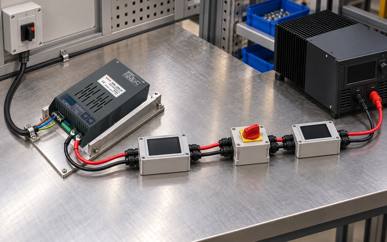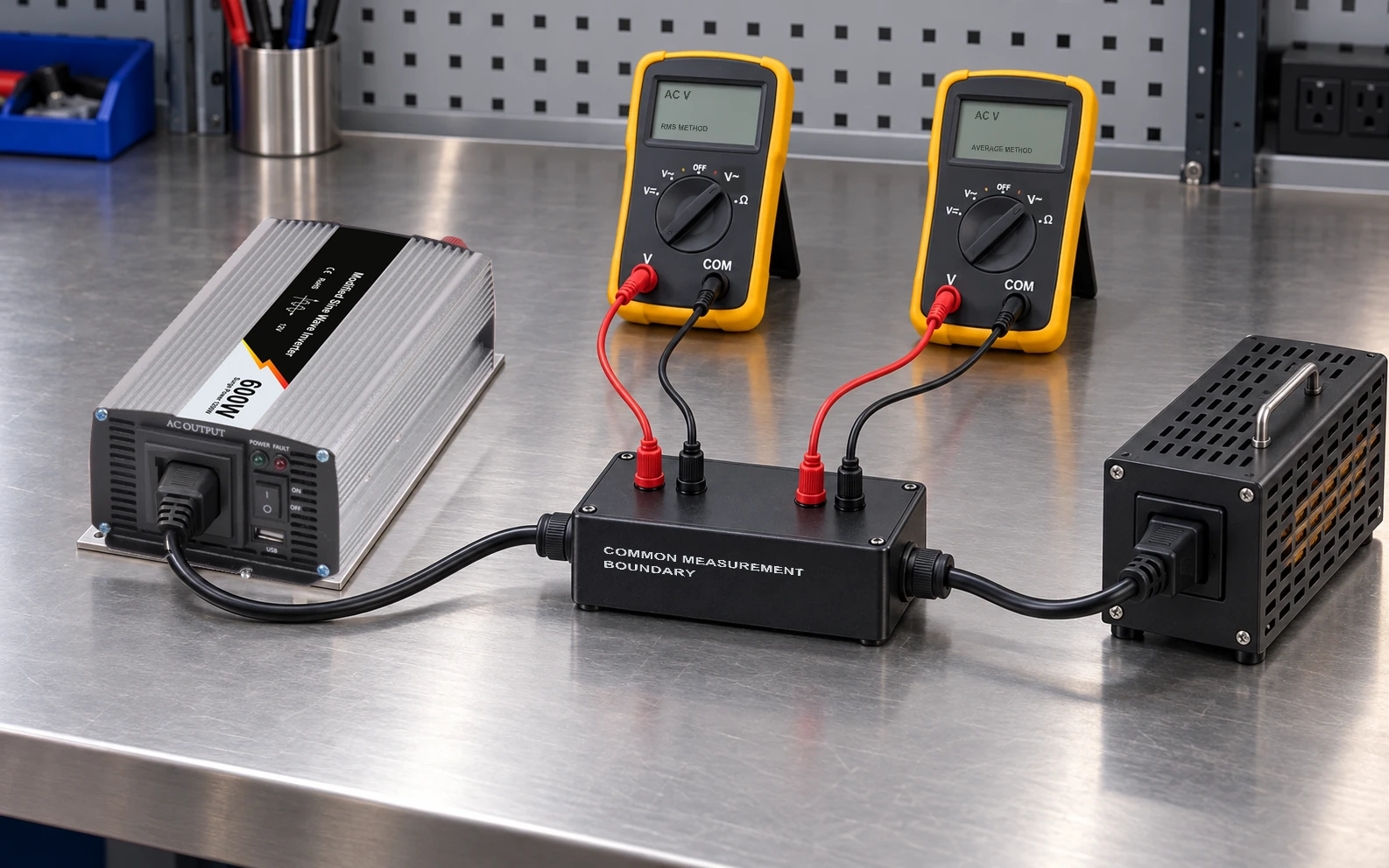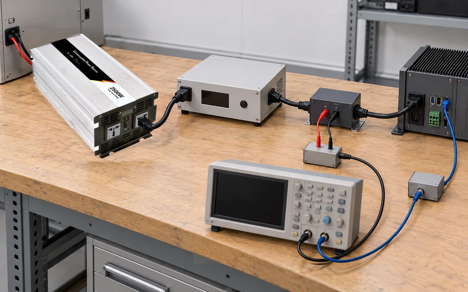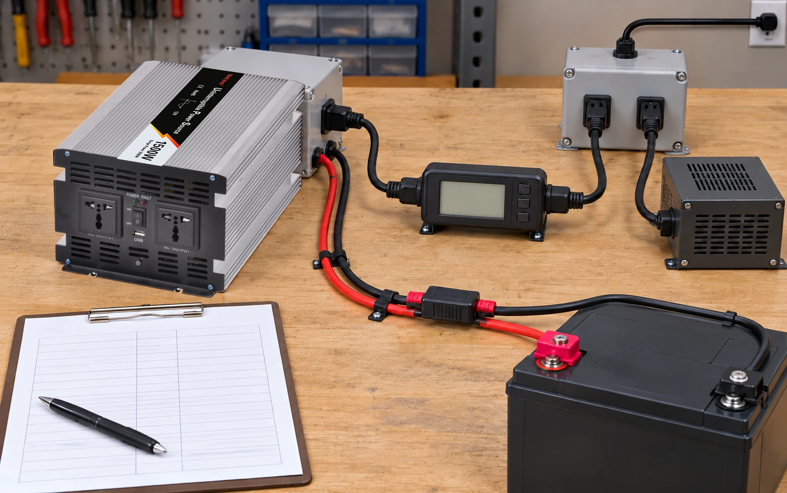
Specify the AC charging source from the charger’s actual input demand and permitted operating states. The inverter’s output wattage is a different rating. Dividing it by the AC source voltage does not establish the charging input current.
An OEM considering the WEHO WHPU-1500 inverter/charger family should request a charger-specific input envelope and build a source budget around it. This article supplies the calculation and record structure without assigning an undocumented charge current or transfer topology.
Identify what the AC input actually supplies
First confirm the exact unit’s permitted functions: charging, inverter operation and any independently documented feed-through state. A charger function alone does not establish that AC input also supplies the output sockets, or that a load is automatically transferred between sources.
Draw the allowed state at system level and list every AC load on the proposed source. Other equipment supplied directly by that source belongs in the source budget even if it never passes through the inverter/charger.
If the source is a generator, an upstream inverter or a shared circuit, retain its continuous capability, voltage/frequency range and relevant transient behavior. Equal nominal watts do not guarantee an acceptable charger-source combination.
Use a charger-specific specification
The WHPU-1500 page identifies the family and 12 V/24 V variants. Its introductory paragraph refers to a different WHPU-1000 unit, while the model table names WHPU-1500. That cross-reference cannot establish a WHPU-1500 charging specification.
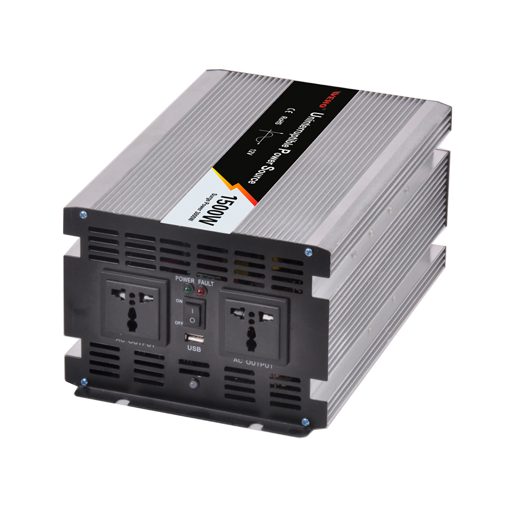
Request the offered revision’s AC input range, maximum RMS current, real power, power factor, startup demand and environmental conditions during charging. The generic“Input current 10 A” table label does not define these quantities by itself.
Do not apply a maximum inverter-efficiency entry to the charger path. Efficiency depends on conversion path and operating point; use charger data or a controlled measurement for the state being budgeted.
Show how charging power becomes AC current
For an initial estimate,PDc=Vcharge×Icharge,PCA=PDc/η, andIAC, rms=PCA/(VAC, rms×PF). Include any additional losses or loads that the chosen boundary requires.
Hypothetical charger example:28 V at 15 A is 420 W DC. At assumed 85% charger efficiency, input real power is 494 W. At 230 V and assumed true PF 0.75, AC RMS current is approximately 2.86 A. These assumed values describe no particular WHPU variant.
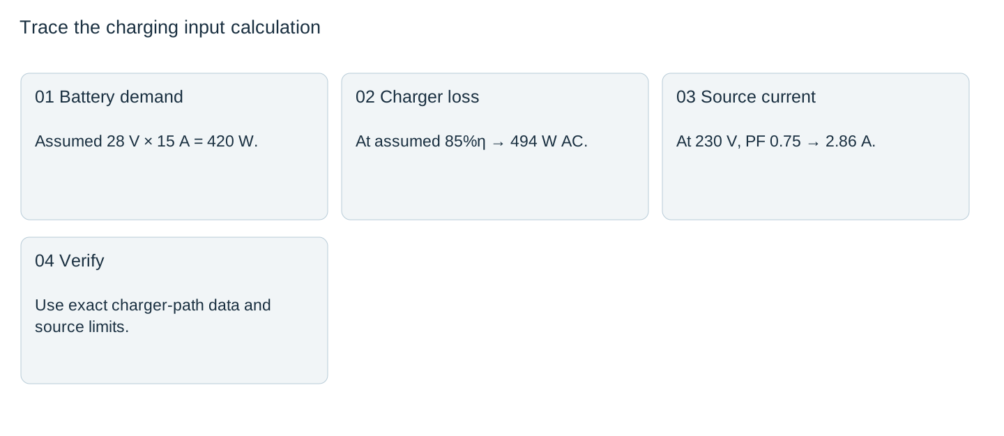

Without the PF term, the same arithmetic would give about 2.15 A and understate the assumed RMS current. Use true power factor, P divided by the product of RMS voltage and RMS current, so waveform distortion is included rather than substituting only a displacement-angle value. This definition does not identify the charger’s internal input topology. Obtain actual data rather than treating either estimate as a protective-device selection.
Budget the charging envelope and the other source loads
Charge voltage and current change through an approved cycle. Identify the condition that produces the relevant maximum input demand, along with input voltage and temperature. A low-current observation near charge completion cannot establish the source requirement at a different battery state.
Sum real power for the real-power budget, but retain RMS current and waveform information for circuit and source review. Separate startup demand from continuous current. A generator or upstream inverter may impose its own limits on nonlinear input current and transitions.
Do not select a breaker or cord solely from the illustrative 2.86 A. Wiring, connector limits, startup, protection coordination and applicable installation requirements still determine the actual AC circuit design.
Verify the intended source and charging state together
Use a suitable AC power analyzer or approved measurement method to record source voltage/frequency, input real power, RMS current, true PF and the charging state. Time-align important source changes with charger and battery behavior.
Record whether other loads are present, and keep the source operating mode with the result. A charger that behaves acceptably on one supply has not automatically been qualified on a smaller generator or an upstream inverter.
Release the source budget only after the offered unit’s defined input demand and the complete assembly’s conditions agree. Revisit the budget when charging limits, battery configuration, other AC loads or source equipment change.
Request the charging-input envelope
Send WEHO the AC source specifications, battery charge requirements, exact DC variant and permitted state diagram. Request WHPU-1500 charger-path input data and evaluate it against the source budget.
AC charging-source budget
| Charging state | DC V/A | AC W / RMS A / PF | Other source loads | Source condition / decision |
|---|---|---|---|---|
Blank project worksheet. Enter verified project data; example calculations above are not measurements.