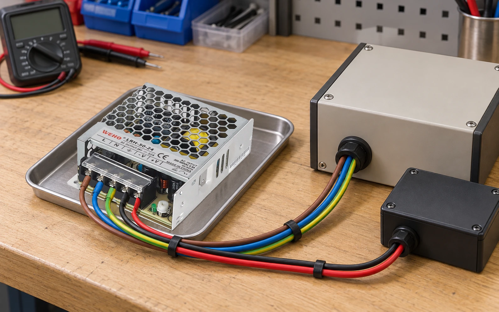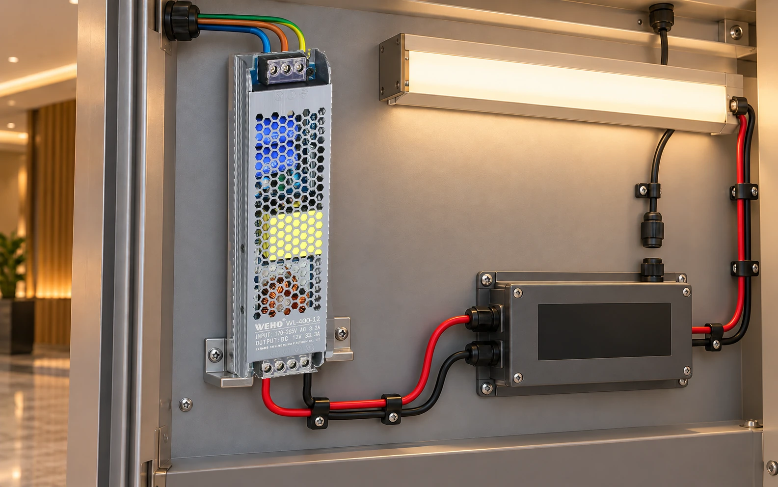
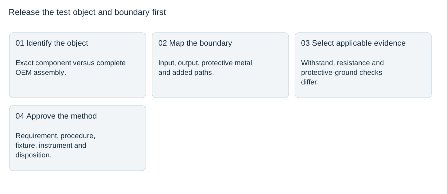
A power supply’s dielectric-withstand statement is not an instruction to apply the same test to every terminal of an assembled machine. Define the test object, insulation boundary, applicable requirement and approved procedure before releasing electrical-safety testing. Keep dielectric withstand, insulation resistance and protective-ground checks as distinct evidence items.
The WEHO LRS-60-12 is the identifiable component example. Its official sheet lists separate insulation-related rows and boundaries. Those component statements do not, by themselves, specify an OEM’s assembled-equipment test or authorize repeated high-voltage testing of an arbitrary connected circuit.
Name the test and the question it answers
SCI’s electrical-safety testing FAQ distinguishes dielectric withstand, insulation resistance, ground continuity and ground bond. Dielectric testing stresses an insulation boundary; insulation-resistance testing evaluates resistance under a specified DC condition. Protective-ground tests address a different path. One result does not silently supply the others.
| Evidence item | Question to define | Common record error |
|---|---|---|
| Dielectric withstand | Which insulation boundary and specified stress are evaluated? | Treating a component rating as a complete-equipment procedure |
| Résistance à l'isolation | Which boundary, DC condition and settled measurement are used? | Calling an ohmmeter continuity result an insulation test |
| Protective-ground evidence | Which protective path and applicable method are evaluated? | Using an output-negative continuity check as protective-ground evidence |
The relevant product or equipment standard and assessment plan determine the actual method and limits. This article provides a document and boundary review, not test voltages, terminal-bridging instructions or an operator procedure.
Map input, output and protective metal separately
Prepare a controlled diagram of the actual assembly. Identify the component input, output, protective-earth connection and any connections added by the OEM. Include data interfaces, filters, surge-protection devices, sensors and external equipment that could change the tested circuit.
A supply terminal called −V is not automatically protective earth. An OEM connection between circuits changes the relevant assembly diagram and may change what a proposed test includes. Do not infer an intended insulation barrier from a photograph or a continuity observation alone. Use applicable component documentation and the responsible equipment design.

Read component statements without enlarging their scope
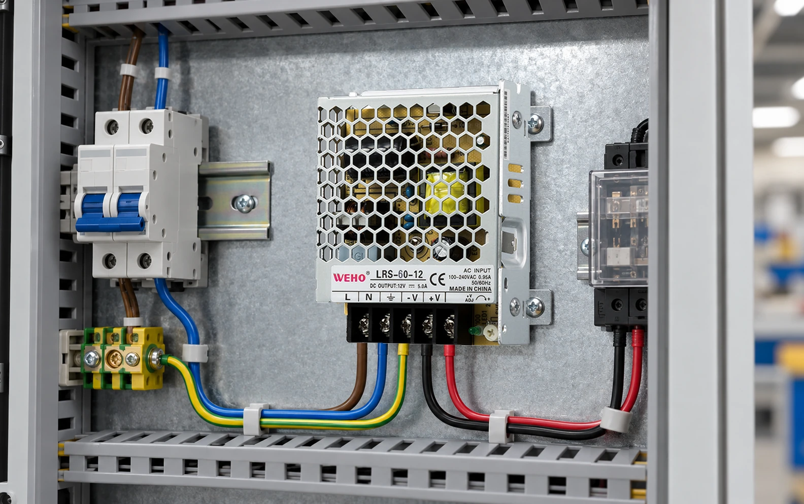
Le WEHO LRS-60 specification distinguishes input-to-output, input-to-frame-ground and output-to-frame-ground in its insulation-related entries. Retain the boundary, test type, conditions and source revision together rather than copying an isolated large voltage into a generic purchase checklist.
The original image reads LRS-60-12, 12 V, 5 A. It is a chassis supply with visible L, N, protective-earth, −V and +V identification. The photograph supports that identity and visible arrangement; it is not a test certificate, evidence of a particular installation class or proof that an assembled machine satisfies its applicable requirements.

Distinguish existing evidence from a new test request
List the evidence already available: applicable component documents, any traceable reports actually supplied, the approved equipment design and any previous authorized test record. Then identify what the proposed incoming or production test must establish. Do not add a new stress test merely because one numerical rating is easy to find.
If another test is required, have the responsible engineering and test owners establish the applicable test configuration and the component’s permitted treatment within it. Keep any isolation or exclusion arrangement explicit in the approved procedure. Repeated tests, altered duration or a substituted AC/DC method are separate changes; they are not authorized by an attractive result on one sample.
Interpret a result with its actual conditions
For a purely illustrative steady DC resistance calculation, 500 V across an assumed 1 µA current corresponds to 500 MΩ because R = V / I. This is not a proposed LRS-60 test setting, an observed leakage value or a passing criterion. It simply shows why voltage, current, units and test identity must remain together in the record.
Real measurements can include charging transients, fixture effects and other paths. Use the approved instrument procedure and observation condition; a momentary reading does not necessarily represent the intended settled result. Keep the raw observation and instrument configuration so a reviewer can understand which quantity was evaluated.
Do not “fix” a failure by raising a trip setting, removing a protective connection or disconnecting a component without an engineering-approved change to the test plan. Classify an invalid configuration separately from a valid failure and retain the disposition.
Hand over the boundary and procedure together
The release package should identify exact component and assembly revisions, the required evidence, circuit boundary, applicable requirement, approved procedure, fixture and instrument, responsible personnel and pass/fail disposition. A laboratory or production team should be able to identify the intended test object without guessing from a family name.
The LRS-60 source set also contains inconsistent input-range statements between the photo, page prose and specification. Those are not resolved by an insulation test and are not used here to approve normal input operation. Request the offered-revision documents for the actual order. Keep this separate from the insulation-test boundary review so a passed test cannot conceal an unrelated selection gap.
A useful enquiry to WEHO states whether the evidence is needed for a component purchase, an incoming check or a completed-equipment assessment. Include the actual circuit diagram and applicable requirement. The result should be a traceable test decision with the correct scope, rather than a single “hipot passed” box that leaves the reader unable to tell what was tested.
Request the applicable LRS-60-12 qualification documents with your proposed equipment boundary diagram, bonded connections, connected electronics and test-purpose list. Have the responsible equipment test engineer confirm the approved method, conditions and acceptance criteria before releasing a withstand, insulation-resistance or bonding test.
Electrical-safety test boundary review
| Evidence item | Boundary and object | Document / procedure revision | Actual condition / observation | Valid result or open issue | Disposition |
|---|---|---|---|---|---|
Blank project worksheet. Enter verified project data; example calculations above are not measurements.