DC-DC soft start should be specified as a controlled startup behavior, with defined conditions and an acceptable current demand on the upstream source. A statement that a converter “has soft start” does not establish its output ramp, its response when the load turns on, or the peak current at its input.
On this page
For an OEM integration engineer, the decision is whether the converter and its load can start while the upstream bus stays within its required limits. Define the ramp and measure the whole sequence before relying on a feature label.
Identify what the soft-start function controls
Depending on the converter design, a soft-start function can act through a reference ramp, duty-cycle limit or other controller behavior. Use the exact model documentation to identify the mechanism and the resulting guaranteed or typical conditions. Do not infer an externally adjustable ramp or a soft-start pin from a generic DC-DC family name.
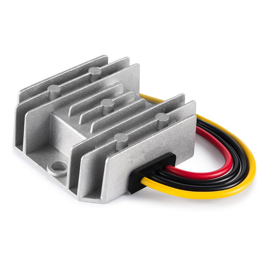
The WEHO WH-C241210 provides a concrete documentation check. Its public specification identifies a non-isolated 24 V-to-12 V, 10 A converter, but does not specify a soft-start ramp or an adjustable soft-start interface. Resolve those missing startup details before qualification. The 30 ms and 10 ms ramps below are hypothetical and are not WH-C241210 specifications.

TI’s isolated-converter soft-start example shows why the real load sequence matters: its controller and startup circuit interact with a load applied during the rise. The example supports evaluating the loaded ramp; its circuitry and performance are specific to that design and do not describe a WEHO converter.
State the start event as well. Applying input to a discharged system and asserting enable on an already established bus can produce different input-current events. A controlled output ramp does not automatically control the initial charging of capacitance directly connected at the converter input.
Separate capacitor charging from useful load current
For a known capacitance and voltage slope, the capacitor current follows IC = C × dV/dt. TI explains this relationship in its discussion of inrush and controlled slew rate. That source uses load-switch examples; it does not establish that every converter implements the same control.
Consider a hypothetical output capacitance of 2,200 µF rising linearly from 0 V to 12 V in 30 ms. The capacitor-charging current is 0.0022 F × 12 V / 0.030 s = 0.88 A. A 10 ms linear ramp would require 2.64 A for the same ideal capacitance and voltage change.
Those values cover only the capacitor term. If an active load draws 2 A during the relevant portion of the ramp, total converter output current would be 2.88 A in the 30 ms example and 4.64 A in the 10 ms example. The load may instead turn on at a threshold or change its demand with voltage. Use its actual profile rather than adding an assumed constant current to every design.
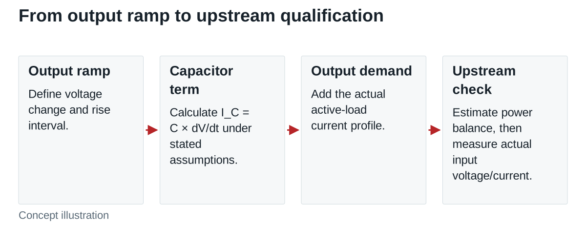
The calculation assumes constant effective capacitance and a linear voltage rise. It does not include current-limit action, voltage- or temperature-dependent capacitance changes, load transients or controller dynamics. It cannot prove that either ramp is achievable or acceptable.
Translate output demand into an upstream question
Input and output currents are different quantities. For a simplified power-balance estimate, IIN ≈ VOUT × IOUT / (VIN × η), using efficiency η at the relevant point. During an actual startup, internal energy storage and switching dynamics can make instantaneous current differ from this estimate.
Continue the invented example at the point where output voltage is 10 V. Assume a 24 V input, 90% efficiency and the 2 A active load. For the 30 ms linear ramp, estimated input current is 10 × 2.88 / (24 × 0.90) = 1.33 A, rounded. For the 10 ms ramp it is 10 × 4.64 / (24 × 0.90) = 2.15 A, rounded. Under the same constant-slope and constant 2 A active-load assumptions, this power-balance term approaches 1.60 A for the 30 ms ramp and 2.58 A for the 10 ms ramp just before the 12 V target is reached. After the ramp, the ideal capacitor-charging term drops out.
These are operating-point estimates during the ramp, not predicted peak input currents. They exclude input-capacitor charging and other internal transients. Use them to identify a question for measurement, then capture actual input voltage and current with the intended upstream source.
Keep delayed start and a slower ramp distinct
Delaying enable can allow an upstream bus to become established before a converter begins demanding power. It does not, by itself, reduce the converter’s demand once enabled. A slower controlled ramp addresses a different part of the sequence.
MEAN WELL’s DC-DC startup compatibility discussion distinguishes soft start from delayed start and explains how a downstream converter demanding power while its input is low can stress an upstream supply. Its LED-system examples are not compatibility evidence for another assembly.
For the OEM design, ask whether the load begins operating before the upstream bus is ready, whether several converters enable together, and whether the intended sequencing survives a restart. Staggering commands changes timing; it still needs validation against each converter’s actual startup current and the shared source response.
Use a startup qualification matrix
| Condition to specify | Record during qualification | Decision supported |
|---|---|---|
| Input applied or enable asserted | Actual start event and initial stored-energy state | Which startup is being qualified? |
| Input range and source behavior | Voltage at converter input, current and upstream limit events | Does the bus remain acceptable? |
| Output capacitance and load sequence | Effective capacitance, load turn-on events, output voltage/current | Does the specified load start correctly? |
| Ramp and validity definitions | Threshold crossings, pauses, dips, overshoot and validity declaration | Is the required output transition achieved? |
| Restart and temperature conditions | Required off interval, residual output, relevant temperatures and repeated starts | Does the result cover the equipment states? |
Define acceptance limits from the equipment requirements and exact converter documentation. Include the permitted input dip, output excursion and readiness time. A slower rise may reduce the ideal capacitor-current term while conflicting with a downstream startup requirement, so “longer is better” is not a complete selection rule.
Approve the converter when its documented function and measured system behavior satisfy the agreed conditions. Hold approval if the ramp definition, input peak or restart behavior is unresolved. Revise the candidate or sequence if the upstream source limits or the load repeatedly resets.
Send WEHO the exact DC-DC model under consideration, input source, output capacitance, load sequence and startup limits so the available model documentation and validation needs can be discussed.