Choose an inverter’s vehicle DC cable and fuse as one circuit: the battery must supply the inverter’s maximum expected input current, the complete cable loop must keep voltage drop acceptable, and the fuse must protect that installed circuit. Dividing AC watts by nominal battery voltage gives a starting estimate, not a finished cable or fuse specification.
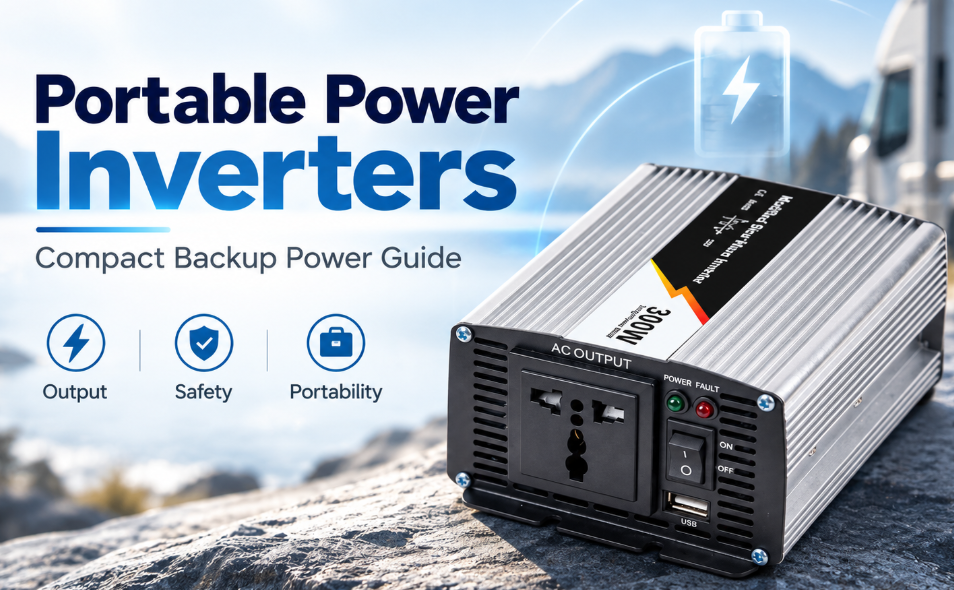
For a vehicle upfitter, the useful question is whether the proposed inverter, battery, cable route and protection work together under the lowest operating voltage and the actual load. The WHM-300-C example below is a photographed 12V modified-sine-wave unit. Its matching C-version sheet lists 300W continuous output and 600W peak; the peak duration is not specified.

Begin with the DC demand, not the AC socket current
An inverter drawing energy from a low-voltage battery needs considerably more DC current than its AC output current. A planning estimate is DC input current ≈ AC output power ÷ (DC voltage at the inverter × efficiency). Use the voltage at the inverter’s terminals, because cable and connection losses reduce what reaches the unit.
At an assumed 85% efficiency, 300W output would require about 29.4A at 12V, or 33.6A at 10.5V. These are calculation examples, not measurements or approved operating points for the illustrated sample. The matching C sheet lists a 10–15.5V input range for the 12V version, but that range alone does not provide a cable rating, a fuse recommendation or guaranteed full-load performance at every voltage.
| Planning input | What the installer needs |
|---|---|
| Continuous AC load | Total simultaneous watts and the inverter’s continuous rating. |
| Starting demand | Peak magnitude and duration, plus the inverter’s documented response. |
| 직류 전압 | Battery operating window and voltage at the inverter under load. |
| 능률 | A suitable operating-point value or a clearly stated conservative assumption. |
Count both conductors and every connection
A cable route described as “two metres to the inverter” normally includes two metres of positive conductor and two metres of return conductor. Both contribute resistance. Lugs, fuse holders, isolation switches and distribution connections add further loss.
For example, a measured or calculated complete-loop resistance of 0.010Ω at 30A gives a 0.30V drop and 9W of heating: V = I × R and P = I² × R. Halving that resistance halves both losses at the same current. This calculation explains why a tidy-looking but long cable route can undermine low-voltage operation.
Cable selection must also consider allowable temperature, insulation, bundling, ambient heat, physical protection and termination capacity. A short cable that meets a voltage-drop target is not automatically suitable thermally. A vehicle chassis return is not a substitute for an assessed return path and the equipment manufacturer’s grounding instructions.

Specify the fuse beyond its ampere number
DC protection selection includes current rating, DC voltage rating, interrupting capacity and time-current behaviour. The protection must suit the battery’s prospective fault current and the installed cable. It also needs to tolerate the permitted starting event without allowing damaging sustained current. The battery-side location and coordination with any upstream protection require a defined circuit design.
그만큼 referenced DC wiring guide explains these general cable and fuse principles. Its product-specific size tables are not WHM-300-C installation specifications. Obtain the matching inverter instructions and the selected cable/fuse data before releasing a vehicle harness.
Check the real terminals before ordering a harness
The illustrated unit has red positive and black negative binding posts on the DC end, with a fan opening beside them. The opposite end carries the AC outlet, switch, indicator lenses and USB port. Keep the fan and connection access usable, support the cable so it does not load the posts, and use the confirmed lug and tightening requirements for the supplied hardware.
Its authentic top label identifies modified-sine-wave output, 12V input and 300W/600W power markings. Another WHM product may have a different input voltage or case revision. A 24V battery system therefore needs the appropriate ordered inverter; cable selection cannot convert a 12V unit into a 24V unit.

Release a complete installation specification
An actionable procurement package lists the inverter revision, battery type and voltage range, maximum continuous and starting loads, positive and return lengths, cable construction and routing conditions, fuse and holder, isolation arrangement, terminations and mounting. Add acceptance checks for loaded terminal voltage, connection heating, protection coordination and secure cable support.

Use WEHO’s product overview to identify the required inverter family, then send the vehicle operating conditions to WEHO. Include the battery voltage, load list, approximate cable route and required AC output voltage/frequency. Request the exact supplied variant’s installation data before choosing the final cable and fuse.
Frequently asked questions
Can I select a fuse from 300W ÷ 12V = 25A?
No. That calculation omits conversion loss, battery-voltage variation, starting behaviour and protection coordination. It is not a complete fuse selection.
Does the 600W peak marking mean the cable only needs to handle that peak briefly?
The marking does not state a duration. The harness must meet continuous thermal requirements and the actual transient duty, while the protection must coordinate with both.
Can a larger fuse solve nuisance trips?
Only after the cause is identified and the cable, holder, battery and inverter limits are reassessed. Increasing a fuse rating without that assessment can remove the cable’s intended protection.