A switching power supply needs a minimum load only when its model-specific operating requirements call for one. For a single-output industrial AC-DC supply, check the documented output-current range and any minimum-load conditions, then verify the equipment’s unloaded, idle and return-to-load states. A 0 A lower limit is useful documentation; it does not, by itself, establish every ripple, transient or environmental limit your equipment needs.
On this page
- Separate minimum output load from no-load input power
- Read the exact current range and its conditions
- A WEHO document example: LRS-350-24
- Qualify the states your equipment will actually enter
- Worked example: a low idle current is still a real load
- Add a preload only when the requirement is established
- Record a decision that purchasing can use
- Discuss your idle-load requirements with WEHO
This guide is for OEM teams qualifying a finished single-output power supply. For interactions between two output rails, use the separate guide to dual-output cross-regulation and uneven rail loads.
Separate minimum output load from no-load input power
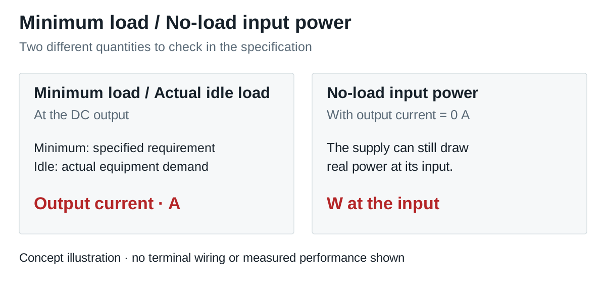
A machine can stop doing useful work while its power supply remains energized. That situation can involve three different quantities:
| Quantity | What it describes | What to record |
|---|---|---|
| Minimum output load | The external load required by the supply’s applicable operating specification | Current or power, model, document revision and conditions |
| Actual idle load | What the connected equipment draws in its lowest normal operating state | Measured or documented current, including optional devices and auxiliary circuits |
| No-load input power | Power consumed at the supply input when no output current is delivered | Real input watts and the measurement conditions |
ROHM’s AC-DC specification guide defines no-load input power as the supply’s own consumption without output current. A small input-power figure therefore does not tell you what minimum external output load is required. Likewise, a controller that stays connected in sleep mode creates a light-load state, rather than a genuinely disconnected output.
Read the exact current range and its conditions
Start with the exact model and suffix. Look for output-current range, minimum load, load regulation, no-load operation and the conditions attached to those entries. A “24 V, 10 A” headline supplies a maximum rating; it does not state the lower operating boundary.
- A range beginning at 0 A: the published current-range field includes zero. Check which other performance specifications apply there and confirm the supplied revision.
- A non-zero lower bound: ask whether it is a mandatory minimum, a recommended operating point or a measurement condition. Resolve that meaning before approving the idle state.
- No lower boundary given: request clarification. Missing information is not evidence for either zero-load approval or a particular preload percentage.
If the equipment can return energy to the DC rail, assess that separately; a minimum-load statement does not specify reverse-energy handling.
A WEHO document example: LRS-350-24
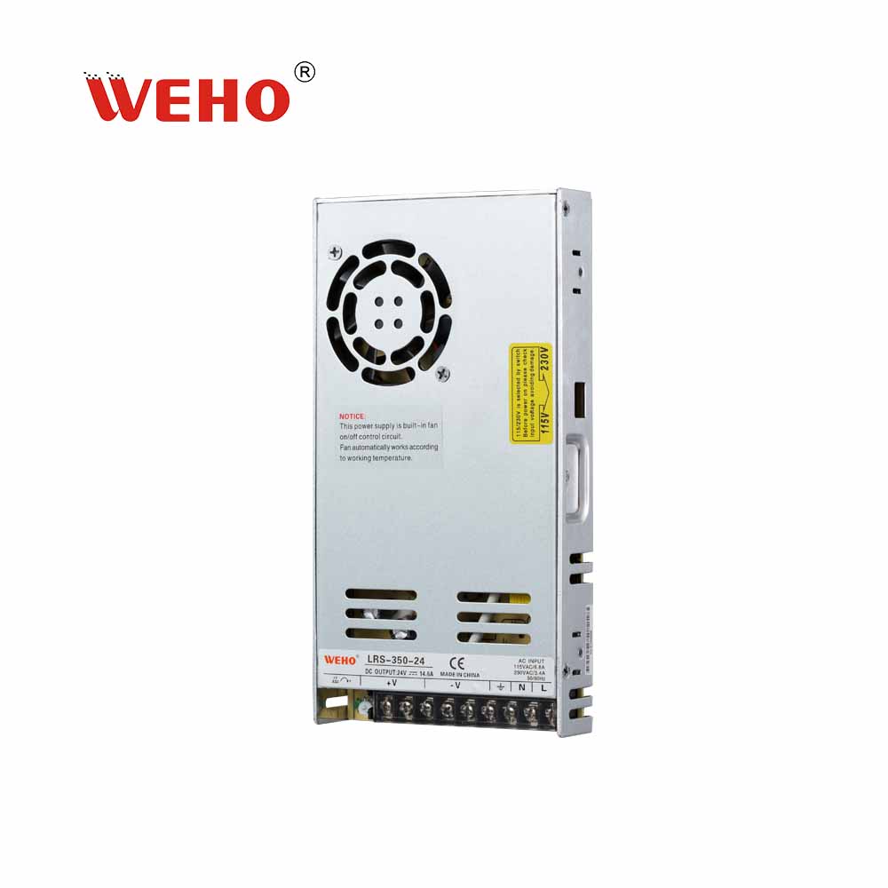
The published WEHO LRS-350-24 product table and the corresponding LRS-350 specification, General Specification table list 24 V and 0–14.6 A. The lower endpoint in that row is 0 A.

Use that row as a starting point for a model-level discussion. The public specification does not provide a complete light-load-to-working-load response record for your installation or show an explicit revision date. Confirm the supplier-issued document identity, applicable low-load voltage and ripple conditions, and recovery requirements for your sample batch before releasing a production design. The photograph identifies the product; it is not a no-load test result.
Qualify the states your equipment will actually enter
Build the acceptance record around operating states. Decide the permitted voltage at the load, ripple measurement method and transient limits before testing. Record input voltage, ambient temperature, cooling, cable arrangement, output setting and sample revision so that another person can reproduce the result.
Some converters change switching behavior at light load. Texas Instruments’ low-voltage boost regulator brief, SLVAFC3, illustrates general light-load efficiency and ripple tradeoffs. It covers a DC-DC boost device rather than an industrial AC-DC supply and does not identify WEHO’s internal topology or operating modes. Judge the selected supply against the agreed output requirements.
| Equipment state | Load condition to define | Evidence needed for acceptance |
|---|---|---|
| Energized with external loads disconnected | Disconnect external auxiliary loads too; record instrument loading permitted by the test method. Treat remaining external consumption as a separate light-load state. | Documented permission, with voltage and ripple meeting agreed limits throughout the required dwell time |
| Return from the unloaded service state | The permitted reconnection, enable or power sequence, initial output condition, load step and connected capacitance; do not assume hot-plug operation is supported | Output excursion, settling and equipment readiness meet the agreed limits, without an unintended protection event |
| Lowest normal idle state | The real minimum current, including configuration tolerances | Output voltage and ripple within the project’s limits at that state |
| Idle to normal operation | Actual current step, rise time, repetition and connected capacitance | Undershoot, overshoot and settling within the load’s agreed limits; no unwanted reset |
| Normal operation back to idle | The largest credible load reduction | Output excursion and settling meet the equipment’s limits |
| Power applied while the equipment is idle | Actual connected idle configuration and subsequent enable sequence | Startup voltage and readiness meet the equipment’s requirements |
| Startup into a permitted no-load state | No external load during initial energization, if required by the project and allowed by the model documentation | Startup output meets the agreed limits before the permitted connection or enable sequence |
A steady multimeter reading alone does not capture ripple or the transient when a load reconnects. Use a measurement setup appropriate to the agreed limits. A qualified person should carry out powered testing using the supply’s instructions; this state table does not specify mains wiring or an internal modification.
Worked example: a low idle current is still a real load
Hypothetical requirement example: a single 24 V rail supplies 0.04 A while its controller sleeps and 2.00 A during operation. A separate service state disconnects all external loads while leaving the supply energized.
The idle output power is 24 V × 0.04 A = 0.96 W. The operating output power is 24 V × 2.00 A = 48 W. Neither calculation gives the AC input consumption, and the 0.04 A idle state does not represent the disconnected service state.
If the selected model is documented for the required zero-load conditions, qualify the disconnected service-state dwell and the permitted return from that state to 2.00 A, as well as the 0.04 A-to-2.00 A idle transition. If its confirmed requirement instead specifies at least 0.10 A, both the idle state and the energized, disconnected service state fall below that boundary and need a documented solution. These are hypothetical requirements, not LRS-350-24 measurements or evidence that this model fits the example.
Add a preload only when the requirement is established
A permanent dummy load turns output power into heat whenever that output is energized. Power Integrations’ AN-61, Step 8 discusses a preload for its particular offline converter design and the accompanying increase in no-load loss. Its component values and design targets do not apply automatically to a finished WEHO supply.
에 대한 separate hypothetical arithmetic example, assume an engineer has established a need for an additional 0.10 A resistive preload at exactly 24 V, after accounting for the connected equipment’s load. The arithmetic gives R = 24 V ÷ 0.10 A = 240 Ω 그리고 P = 24 V × 0.10 A = 2.4 W. Those numbers are not a resistor selection: voltage and resistance tolerances, worst-case dissipation, ambient temperature, mounting and component derating still need engineering review. The preload also consumes capacity when useful loads are operating.
First compare a supply whose documented load range already covers the equipment states with any proposed preload solution. If a preload is necessary, qualify the revised assembly and include its heat and energy cost in the equipment design.
Record a decision that purchasing can use
- GO: the confirmed model conditions cover the minimum-load state, and the agreed state and transition checks pass.
- HOLD: the meaning of the current-range field, the applicable revision, a low-load limit or an essential measurement remains unresolved.
- CHANGE: a credible equipment state falls outside the documented operating conditions or agreed output limits. Evaluate another model or an engineered change, then repeat the affected checks.
Keep the model and revision, minimum and disconnected-load states, dwell times, input and environmental conditions, voltage and ripple limits, transition records and decision together. This turns “can it run without a load?” into a requirement that a supplier and an OEM can verify.
Discuss your idle-load requirements with WEHO
Send the model under review, output voltage, lowest connected current, any fully disconnected state, expected dwell time and the return-to-load step. Include the required input range, enclosure temperature and output limits so the relevant model documentation and validation needs can be discussed.