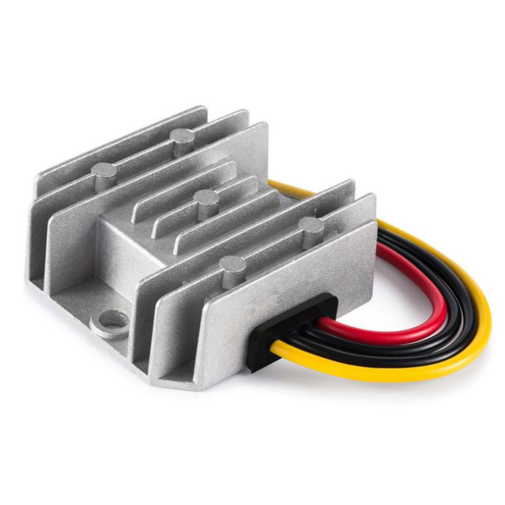
A synchronous buck converter uses a controlled switch in the rectifying position where a conventional non-synchronous buck uses a diode. That difference affects losses and possible current behavior, but it does not establish the efficiency, light-load performance or reverse-current protection of a finished module. Compare documented operating points and control behavior before choosing a supplier or releasing a substitute.
For an OEM buying a complete DC-DC converter, the useful decision is which candidate meets the equipment’s operating envelope. An unfamiliar topology label is not a reason to infer the internal design of a WEHO product. If that information is needed for qualification, request model-specific documentation.
On this page
- Understand what the topology name actually identifies
- A loss calculation helps ask the right thermal question
- Make the lowest operating state part of the comparison
- Keep topology and acceptance evidence in the same record
- Separate a rectifier’s behavior from terminal reverse protection
- Release the candidate on documented operating points
Understand what the topology name actually identifies
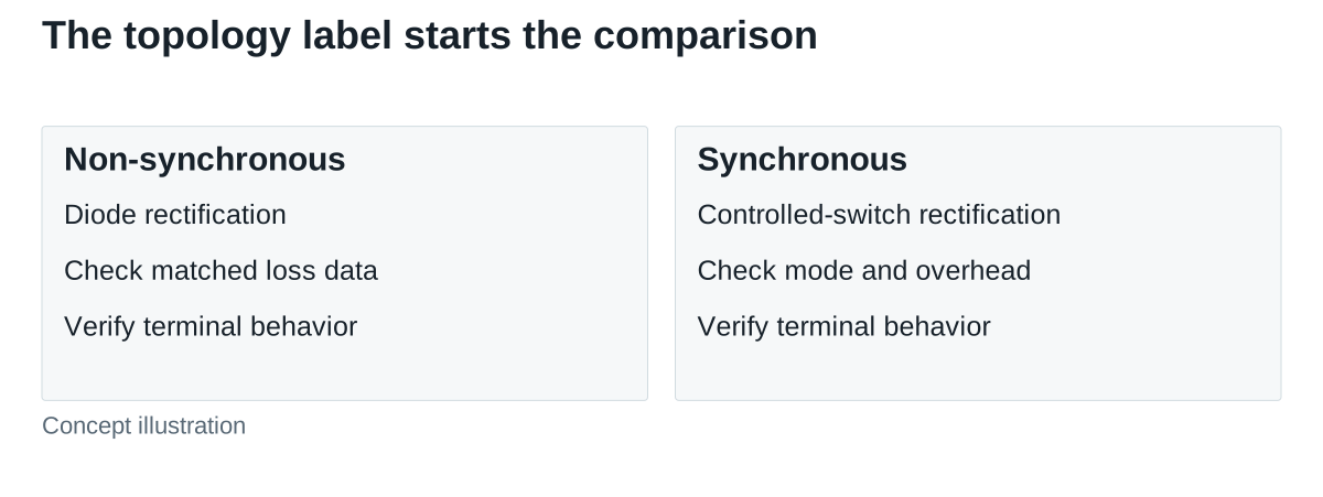
Murata’s rectification comparison identifies diode rectification and synchronous rectification by the component used in the commutating position. A controlled MOSFET can reduce rectification loss, while its control adds requirements that a simple diode does not have.
This distinction is narrower than saying “synchronous is always better.” The result depends on duty cycle, current, device resistance, diode drop, switching behavior and control overhead. Texas Instruments’ comparison of synchronous and non-synchronous buck converters demonstrates that the preferred efficiency result can change with the operating point. Those measurements describe the circuits tested in that paper, not a WEHO module.
A loss calculation helps ask the right thermal question
Hypothetical component-loss comparison: assume an idealized buck conversion from 24 V to 5 V at 3 A. Use an ideal duty ratio of D = 5 ÷ 24 ≈ 0.2083. Assume continuous inductor current with small ripple, an illustrative diode drop of 0.45 V and an illustrative low-side MOSFET on-resistance of 0.025 Ω.
The simplified diode conduction estimate is 0.45 × 3 × (1 − 0.2083) ≈ 1.07 W. The corresponding low-side MOSFET conduction estimate is 3² × 0.025 × (1 − 0.2083) ≈ 0.18 W. These are assumed component conditions, not measured converter losses or temperature rises.
The difference does not equal a promised module-efficiency gain. The estimates omit switching, gate-drive, dead-time, magnetic, capacitor and controller losses. Resistance and diode drop also vary with real device conditions. A purchaser should use this calculation to request matched thermal and efficiency evidence, rather than turn it into a product ranking.
Make the lowest operating state part of the comparison
A machine may spend substantial time below its normal production load. Request efficiency or input-loss information at the actual minimum, typical and peak operating points, with the same input voltage, output setting, ambient conditions and cooling arrangement for both candidates.
Identify the supported control modes and how the ordered variant selects them. Forced continuous operation, diode emulation or other light-load strategies can create different current and ripple behavior. Do not assume those modes exist, can be selected externally, or operate at a particular threshold simply because the module is described as synchronous.
Mode transitions also matter when a receiver is sensitive to low-frequency ripple or the equipment wakes repeatedly from idle. Record the real state sequence and its required output limits. A single maximum-efficiency number cannot answer whether the equipment will remain within those limits.
Keep topology and acceptance evidence in the same record
| Decision area | Evidence to compare | Do not infer |
|---|---|---|
| 정류 | Manufacturer-confirmed design or declared module information | Topology from a case photograph or series name |
| Loaded loss | Matched input, output, current and thermal conditions | System efficiency from one device’s conduction estimate |
| Idle behavior | Permitted minimum load, mode and relevant output observations | Light-load results from full-load efficiency |
| Current direction | Allowed terminal currents during operation, disable and power loss | Reverse blocking from the word non-synchronous |
| Transitions | Defined enable, startup and load-change cases | Acceptable recovery from a steady voltage reading |
| Assembly fit | Input/output limits, installation, cooling and protection documents | Interchangeability from an equal wattage rating |
Use this record to compare actual candidates, not two idealized circuit drawings. A finished module can contain additional switches, protection or control functions. Those features, and the system around them, determine what its terminals will do.
For a finished-module identity check, WEHO WH-C241210 has a public specification listing an 18–32 V input range and a 12 V, 10 A output. Those entries identify an electrical candidate; neither they nor its finned enclosure identify synchronous or diode rectification. Keep the topology field unconfirmed until applicable manufacturer information resolves it, and compare the finished module at the required operating points.

Separate a rectifier’s behavior from terminal reverse protection
A diode in the conventional rectifying position constrains current through that branch. It does not prove that every possible path through a complete converter blocks output-to-input current. An externally energized output can, for example, feed an unpowered input through a high-side MOSFET body diode in some step-down implementations, as TI’s output-powering guidance explains. Likewise, a synchronous stage’s ability to carry negative inductor current does not prove that the product is an approved bidirectional power converter.
For a replacement decision, ask which externally imposed voltage or current conditions are permitted when the input is present, absent or disabled. Include residual or externally held output voltage in that allowed-state review. If the manufacturer supplies no applicable answer, keep that condition open. The wider system decision about returned energy belongs in a separate review; it should not consume the topology comparison.
Release the candidate on documented operating points
A useful result identifies the exact converter and revision, required input/output envelope, relevant control behavior, matched loss evidence and remaining exceptions. Preserve the actual sample configuration and acceptance limits. If a topology advantage disappears at the equipment’s important operating points, document that result rather than preserving the original preference.
Send WEHO the conversion voltages, load-state schedule, thermal conditions, permitted current directions and the evidence required for a proposed module. A model-specific discussion can then address the real requirement without inventing an internal topology from a marketing term.