



Key Engineering Takeaways
- WHPU-500 12 V columns list a 10.5 ± 0.5 V alarm and 10 ± 0.5 V low-voltage protection threshold.
- The published function describes an alarm first, then shutdown as voltage continues falling.
- Overlapping numerical intervals do not overturn that sequence or specify a minimum warning time.
- Specify the required alarm-to-output-loss sequence and verify the delivered configuration.
Why is a nominal voltage gap insufficient for a warning requirement?
A voltage difference is not a time specification. A buyer who needs a warning before loss of AC output must consider threshold tolerances, the rate of input-voltage change and the behavior of the alarm and protection functions. Subtracting two nominal voltages leaves those conditions unresolved.
그만큼 WHPU-500 inverter and charger information lists separate alarm and protection thresholds for its 12 V and 24 V input columns. This article examines the published 12 V values.
The low-voltage function description states an alarm first, followed by shutdown as voltage continues falling. That qualitative sequence is accepted here; the separate question is whether a minimum warning duration is documented for the required conditions.
For an OEM writing a warning requirement, the decision is whether the available evidence supports a minimum lead time. If it does not, specify the required behavior and obtain applicable information or qualification evidence rather than assuming a favorable result.
What do the published 12 V thresholds actually say?
The product table lists low-voltage alarm at 10.5 ± 0.5 V and low-voltage protection at 10 ± 0.5 V in the 12 V columns. It also lists a separate low-voltage recovery value of 12.3 ± 0.5 V. These are different functions and should remain separate in the requirement.
The nominal falling-voltage difference is 10.5 V − 10.0 V = 0.5 V. That calculation is correct as a comparison of nominal values. It becomes misleading only when used as a guaranteed separation or converted directly into a promised warning time.
The cited table does not describe how alarm and cutoff tolerances track within a unit. Nor does it provide a complete minimum warning-time specification for every input trajectory and load. Its alarm-first functional statement remains relevant. Do not infer independent threshold extremes, perfect tracking, or a minimum delay that the table does not specify.
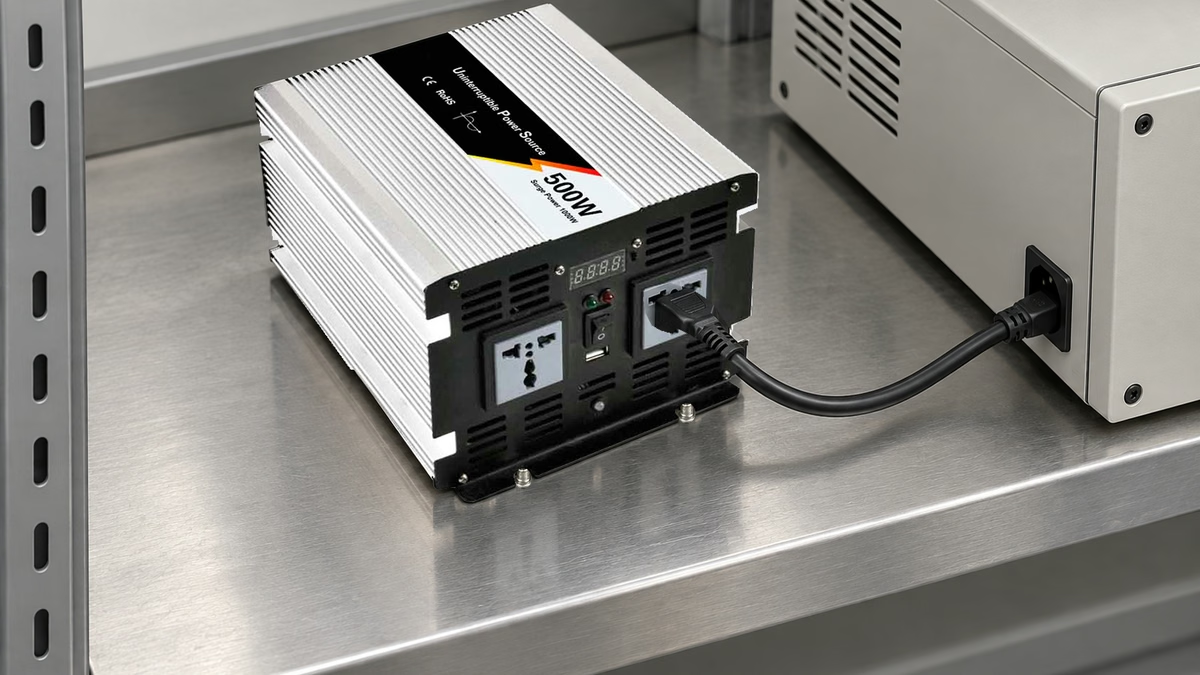
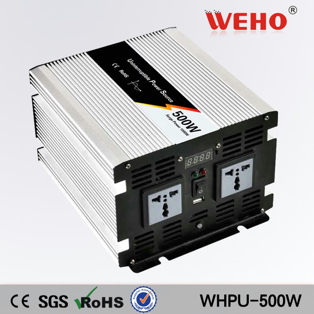
The official photograph shows the 500 W family form and a WHPU-500W model banner. It does not establish which 12 V or 24 V table column applies to a delivered unit. Confirm the complete input/output configuration; the photograph does not establish the internal implementation or timing of protection functions.
How do the tolerance intervals change the conclusion?
Use a Published-Threshold Interval Example based on the 12 V table. This is interval arithmetic on manufacturer values, not a measurement of a WHPU-500.
Alarm interval = 10.5 V ± 0.5 V = 10.0–11.0 V.
Protection interval = 10.0 V ± 0.5 V = 9.5–10.5 V.
Their numerical overlap is 10.0–10.5 V. The ranges therefore do not, by themselves, establish a positive guaranteed separation. A conservative uncoupled comparison gives 10.0 V − 10.5 V = −0.5 V. That bound is not a prediction of a real unit or a reason to contradict the stated alarm-first behavior; it shows why separate tolerance ranges cannot quantify the guaranteed lead time.
| 기능 | Published 12 V value | Calculated interval | Timing information to confirm |
|---|---|---|---|
| Low-voltage alarm | 10.5 ± 0.5 V | 10.0–11.0 V | Alarm indication and response timing |
| Low-voltage protection | 10.0 ± 0.5 V | 9.5–10.5 V | Minimum alarm-to-output-loss duration |
| Low-voltage recovery | 12.3 ± 0.5 V | 11.8–12.8 V | Complete output-return sequence |
The practical result is a distinction between function and timing. Use the stated alarm-first behavior as the functional description. An application that needs a guaranteed duration still requires timing evidence under its specified input and load conditions.
Ask whether the offered revision specifies a minimum lead time or voltage separation under the required conditions. A timing statement tied to the actual voltage trajectory is more useful to that requirement than another nominal threshold value.

Swipe horizontally on a small screen, or open the full-size diagram.
When can a voltage gap be converted into an illustrative time?
A voltage gap can be converted into time only under a defined voltage trajectory and response model. For an ideal linear fall with slope magnitude r, the interval between two fixed crossing voltages is:
Crossing interval = (alarm voltage − cutoff voltage) ÷ r.
에 대한 Hypothetical Linear-Ramp Example, assume fixed thresholds exactly at 10.5 V and 10.0 V, a constant fall of 0.1 V/s and no additional event delays. The crossing interval is 0.5 V ÷ 0.1 V/s = 5 s. With the same ideal thresholds and a fall of 1 V/s, it becomes 0.5 s.
Neither figure is a WHPU-500 warning-time specification. The example assumes away threshold variation and response delays to show why the input trajectory matters. A fast step can cross both nominal levels within an interval that a slow ramp does not represent.
The relevant alarm may also need to be noticed or captured by another system. Define whether the requirement concerns a local indication, an audible event, a documented electrical signal or a machine response. Do not infer a remote alarm interface from a protection-table description.
How should the required sequence be verified?
- Identify the actual 12 V configuration, applicable product revision and intended load. Record the required warning event and what counts as loss of usable output.
- Define the input-voltage trajectories relevant to the equipment. Include their starting conditions, ramp or step characteristics and permitted operating limits.
- Establish synchronized observation of input voltage at the inverter, the applicable alarm event and output behavior. Select equipment and timing resolution appropriate to the requirement.
- Perform the authorized qualification procedure using a suitable controlled source and load. Do not deliberately over-discharge a battery to create an undocumented test condition.
- Record the event order, observed thresholds and elapsed time with the test conditions. Compare the results with the explicit requirement rather than with the nominal 0.5 V subtraction alone.
- Evaluate the separate recovery sequence if the equipment depends on it. Keep alarm, output loss and output return as distinct observations.
Use qualified personnel and the equipment safety and isolation procedures. The public product page is not a complete installation or destructive-test instruction. Avoid repeated cycling outside the applicable operating conditions while trying to discover an undocumented margin.
What should procurement ask the supplier to clarify?
Ask for the offered revision's applicable threshold conditions, definition of the alarm event and any guaranteed minimum alarm-to-output-loss time. If the machine requires a minimum warning duration, provide the input trajectory and load conditions that make that duration meaningful.
그만큼 WHPU-500 12 V protection reference provides the published starting values. It does not replace the complete ordering record or the OEM's qualification of the required sequence.
Use the threshold and event-sequence worksheet to keep published intervals, supplier clarifications and actual observations separate. Send WEHO the warning-time requirement with the exact configuration, voltage trajectory, load and event definition. This makes the unresolved question specific enough to evaluate.
Engineering FAQ
Does the 0.5 V nominal gap guarantee several seconds of warning?
The nominal gap does not guarantee a warning time. Time depends on the actual threshold relationship, input trajectory and event response. The separate tolerance intervals alone do not quantify a minimum lead time; they do not invalidate the published alarm-first function.
Does interval overlap prove that shutdown happens first?
No. The page describes an alarm-first low-voltage function. Overlapping numeric intervals do not disprove that stated sequence, and they do not quantify a minimum time. Obtain applicable timing information and verify the required behavior under defined conditions.
Can a slow-ramp result qualify a fast voltage step?
A slow ramp and a fast step are different input events. Qualify the trajectories relevant to the equipment and use observation timing capable of resolving the required alarm-to-output-loss interval.
Is the recovery threshold another warning threshold?
Recovery is a separate return condition. Its voltage value does not establish a minimum falling-voltage warning duration or the complete output-return sequence. Record recovery independently if the equipment depends on it.



