



Do not assume that a T-120B remains within its published operating conditions when one rail falls to almost zero load. Its specification lists a lower current boundary on all three outputs: 2 A at +5 V, 0.5 A at +12 V and 0.2 A at −12 V. Check the least-loaded state of each rail, especially when an analog receiver sleeps or is disconnected for service.
The immediate question is not whether the machine consumes less than 120 W. It is whether each powered rail still carries a load within the documented range. This guide helps an analog-instrument designer identify an idle-state shortfall, evaluate possible remedies and state the evidence needed before approving a design.
What the T-120B current range actually says
The WEHO T-120 product page and the T-120B column in the official specification sheet agree on the following voltage and current combinations. Treat the lower ends as selection boundaries. They are not a claim that an output becomes safe to touch, switches off or supplies zero volts below that current.
| Output | Published T-120B range | Least-loaded state to investigate |
|---|---|---|
| CH1: +5 V | 2–11 A | Logic standby, disabled boards or optional modules absent. |
| CH2: +12 V | 0.5–4.5 A | Analog stages disabled or receivers disconnected. |
| CH3: −12 V | 0.2–1 A | Negative-rail amplifier bias only, standby or service. |
The current-range row does not document a no-load regulation envelope for an arbitrary receiver. If your required state lies below it, obtain a written statement covering that state or change the design. A voltage reading taken once on an unloaded bench unit does not extend the published operating range to every input, temperature or production revision.
Also keep upper rail limits and total simultaneous power in the separate load budget. Passing the minimum-load check does not authorize the sum of all listed rail maxima.
A negative-rail idle example
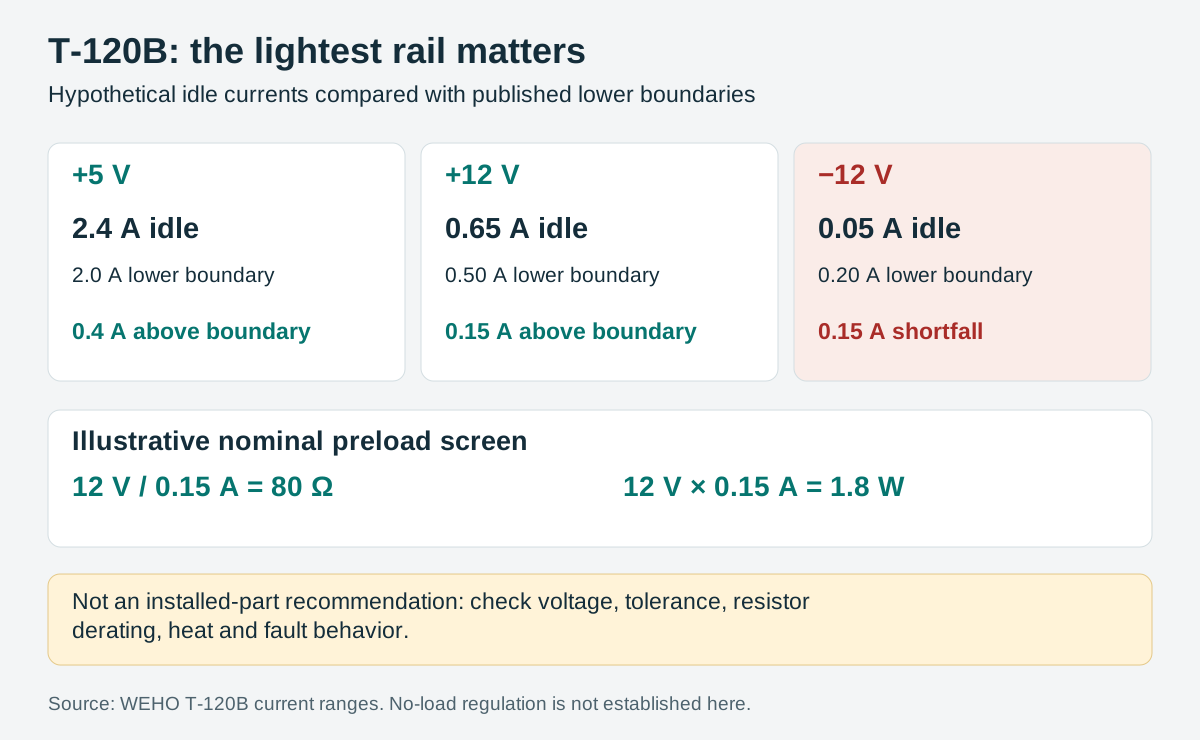
Consider a hypothetical instrument whose idle demand is +5 V at 2.4 A, +12 V at 0.65 A and −12 V at 0.05 A. The two positive rails exceed their published lower boundaries. The negative rail is short by 0.20 − 0.05 = 0.15 A. The fact that only 20.4 W is being used at nominal rail voltages does not remove that shortfall.
Repeat this review for each enabled mode, including calibration, standby and a missing optional board. Use current magnitude for a negative rail: “−12 V at 0.05 A” describes a 0.05 A load on that rail, not a negative contribution to the machine’s power sum. Identify the receiver’s actual reference and approved operating limits before measuring it.
If idle current is an estimate, make the uncertainty explicit. A data-sheet typical bias current is not a guaranteed minimum. A lower temperature, a different board revision or a disabled channel may further reduce the load. The review should identify the smallest credible current rather than the most convenient nominal value.
Choose a documented remedy before adding a preload
| Option | When it may be useful | Evidence to obtain |
|---|---|---|
| Confirm lower-load operation | The required instrument state is below a listed boundary. | Exact model/revision, all rail loads, input, temperature and allowed output variation. |
| Keep an intentional functional load | The machine already has a load that can remain active. | Guaranteed minimum consumption in every relevant mode; receiver and control requirements. |
| Engineer a preload | A deliberate dissipative load is acceptable. | Tolerance, voltage range, resistor derating, mounting temperature and failure response. |
| Change the supply architecture | Idle demand is inherently small or changes widely. | A supply or local conversion arrangement specified for the required conditions. |
Do not bridge the positive and negative rails just to “use the spare capacity.” That changes the load path and voltage across the added component. A preload must be designed against the intended rail and reference, with protection and installation reviewed by the equipment designer. The diagram here is an arithmetic review aid, not a terminal wiring instruction.
A resistor calculation is only the first screen
For the hypothetical 0.15 A shortfall at a nominal 12 V magnitude, R = V / I = 12 / 0.15 = 80 Ω, and P = V × I = 1.8 W. Those numbers explain the scale of a possible preload; they are not a released resistor value or a recommended wattage.
At the lowest permitted voltage magnitude, the highest actual resistance must still produce the required additional current. At the highest voltage magnitude, the lowest resistance sets the highest dissipation. Include resistor tolerance, its temperature coefficient, actual negative-rail voltage and the receiver’s lowest guaranteed current. With a fixed resistor, use I = |V| / R and P = V² / R for both ends of the design range.
Then apply the resistor manufacturer’s temperature and mounting derating, account for heat near sensitive analog circuits and examine what an open or shorted preload would do. A component marked above 1.8 W is not automatically acceptable in a warm enclosed assembly. If the resulting heat or fault behavior is unattractive, a supply designed for the lighter load may be the better engineering choice.
Release the idle condition as a separate test case
Document the actual currents of all three rails during the lowest-load state and check rail voltages at the receivers. Record input conditions, enclosure temperature, board population and the duration of standby. If adding a preload, include its measured temperature and the production part number in the record.
Use the receiver’s approved limits to judge the result; do not substitute the absence of a reboot or visible fault. A stable display alone does not show that an analog front end is within its required supply range. Capture the quantities that matter to the application, such as receiver voltage and the instrument’s specified offset or error check.
The release record should distinguish operation within published rail ranges from a separately documented exception. Reopen it if firmware changes the sleep mode, a board is removed, or a resistor value or supplier changes. That keeps a quiet standby state from becoming an unrecorded change to the power system.
Use the project record
Open the blank T-120B minimum-load and idle-condition record to record your conditions, evidence and decisions. The worksheet contains no pre-approved result.
When asking WEHO about the T-120B triple-output supply, provide the minimum and maximum current on each rail, including standby. Ask specifically about any state below the published lower boundary and the conditions required to support it.




