Key Engineering Takeaways
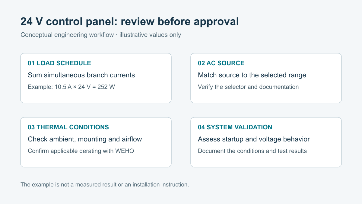
- Add the 24 V currents that can operate simultaneously; calculate output power using the operating voltage, not the series name alone.
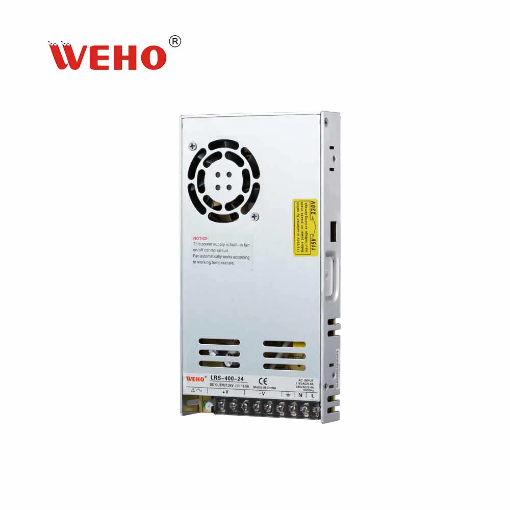
- The published LRS-400-24 table lists 24 V and 0–16.5 A, equivalent to 396 W at the nominal voltage. Actual allowable loading still depends on the applicable unit documentation and operating conditions.
- The published AC input uses separate 90–132 V AC and 180–264 V AC ranges selected by a switch; verify the actual source and correct setting before energizing.
- Treat thermal conditions, startup demand and enclosure airflow as separate checks. The published temperature range is not evidence of full output across that entire range.
Begin With a Real Operating-State Table
A panel builder may need one 24 V source for control electronics, field interfaces and other auxiliary loads. The engineering decision is whether the proposed power supply fits the actual simultaneous operating states, the available AC source and the enclosure’s thermal conditions.
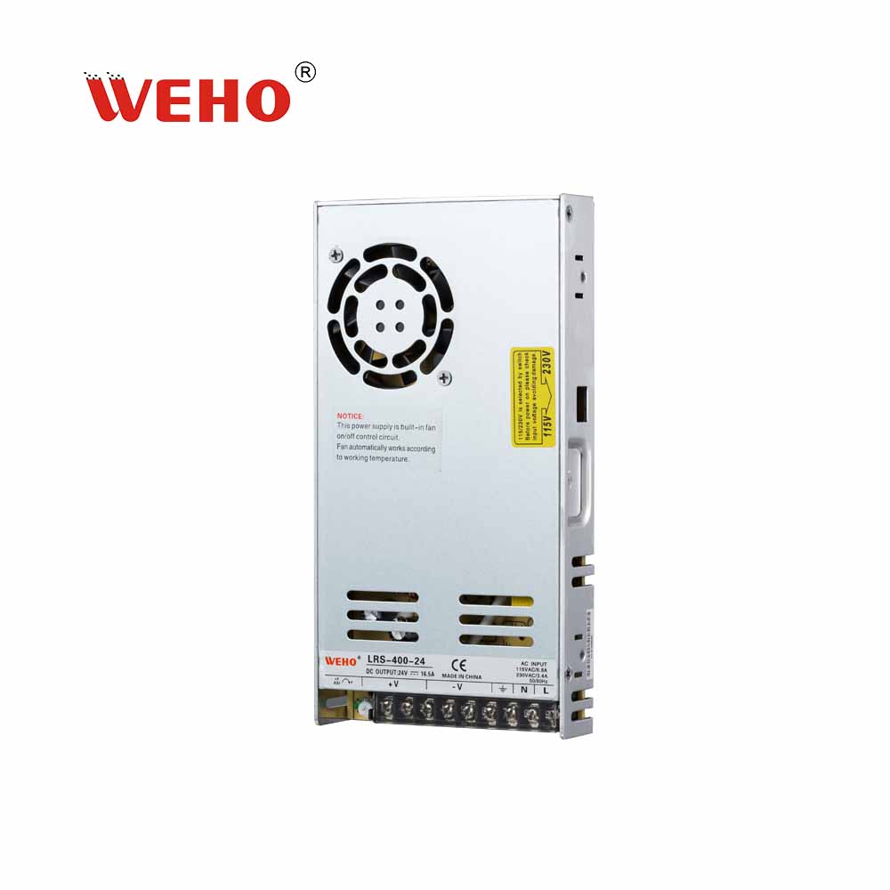
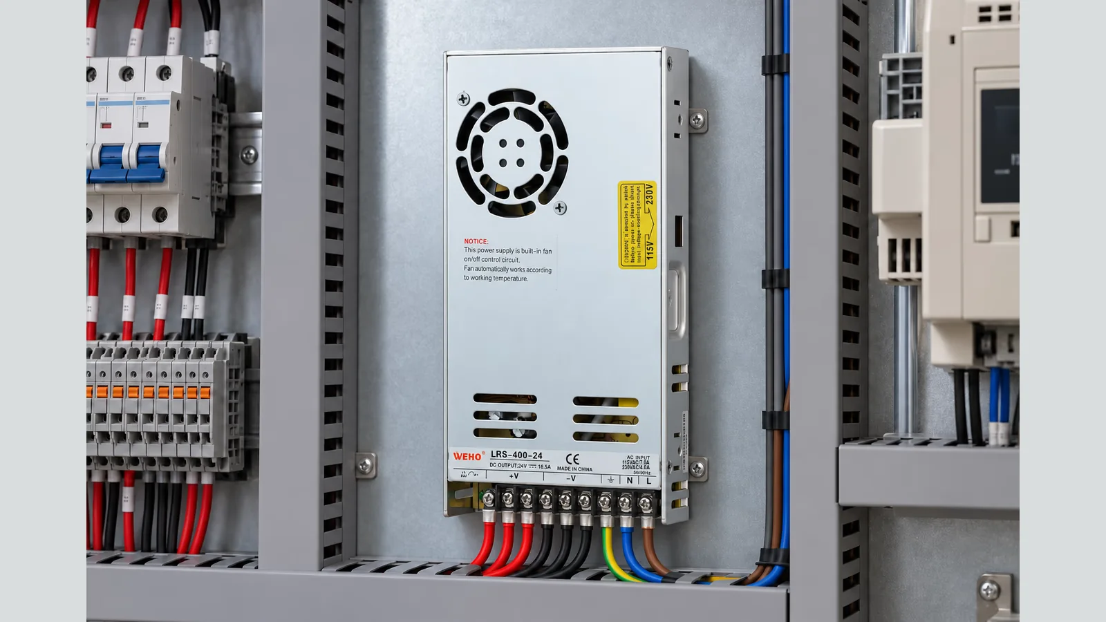
The WEHO LRS-400-24 product listing includes the 24 V model in the LRS-400 series. Use the model-specific column and the applicable unit documentation rather than treating the 400 W family name as the rated output of every voltage version.
A reliable schedule identifies each branch, its voltage and its highest relevant sustained current. Record normal operation, maintenance mode and any state in which additional loads operate together. The worst operating state is the one with the highest credible simultaneous demand, not necessarily the sum of unrelated equipment nameplates.
Calculate a 24 V Simultaneous Load
Hypothetical Control Cabinet Load Model: the following currents are assumptions for a calculation exercise, not measurements, customer data or verified compatibility claims. Assume all four branches run together at a nominal 24 V.
| Example branch | Assumed sustained current | Basis to replace with project data |
|---|---|---|
| Control electronics | 4.0 A | Documented current at the equipment’s actual supply voltage |
| Field interfaces | 3.0 A | Concurrent devices and their load documentation |
| Auxiliary control loads | 2.0 A | Normal operating state and branch losses |
| Additional 24 V loads | 1.5 A | Actual devices and simultaneous duty |
| Total | 10.5 A | 4.0 + 3.0 + 2.0 + 1.5 A |
Swipe horizontally to see the full table →
At the assumed nominal voltage, the estimated output demand is 24 V × 10.5 A = 252 W. This calculation does not include a measured startup waveform or demonstrate how any individual branch behaves.
The WEHO LRS-400 series specification sheet lists 24 V and 0–16.5 A for LRS-400-24. Multiplying those nominal values gives 396 W, while the series is described as 400 W. The model-specific calculation makes the comparison explicit; it is not a claim about the output available in every environment.
As a planning illustration only, suppose the design team chooses to use 80% of a supply’s confirmed available capacity for its sustained load. The example would require 252 W ÷ 0.8 = 315 W of available capacity under the relevant conditions. The 80% ratio is an example project choice, not a WEHO requirement, thermal derating curve or guarantee.
Compare 315 W with the supply’s condition-specific available capacity only after checking the applicable datasheet revision and thermal guidance. The nominal calculation makes this model a candidate for further evaluation; it does not approve the installed design.
Separate Startup Demand From Sustained Current
A steady operating-state sum does not capture every startup condition. Input capacitors, contactor or solenoid circuits and electronic equipment may draw different currents when power is applied. Obtain the amplitude and duration from the relevant load documentation or a defined measurement rather than assuming each peak equals its sustained value.
Create a startup sequence showing which branches can begin together, the expected duration of each event and the required output-voltage behavior. If a controller must remain ready while another load starts, define its minimum acceptable voltage and timing using the controller’s own documentation.
The supplier’s sheet describes protection behavior, but the available wording is not a substitute for an application-specific startup envelope. In particular, do not turn a protection percentage into an allowable peak-current duration or rely on automatic recovery as a normal operating mode. Ask WEHO for clarification if the startup demand approaches the documented limits.
Check the AC Supply and Input Selector
The published LRS-400-24 specification identifies two AC input ranges: 90–132 V AC and 180–264 V AC, selected by a switch. They are distinct ranges, not a single uninterrupted 90–264 V AC operating range. The applicable source voltage must remain within the range corresponding to the actual setting.
For example, a nominal 120 V AC source falls within the lower range and a nominal 230 V AC source falls within the upper range. The nominal value is only a starting point: record the expected minimum and maximum voltage at the equipment, frequency and destination market before completing the check.
The interval between 132 V AC and 180 V AC is not included in either published AC range. A system subject to an expected input outside the selected range needs a different documented solution; do not bridge the gap with an assumption about how the unit will behave.
The documentation says the range is selected by a switch. This article does not establish the selector’s position, labels or safe adjustment procedure on a particular unit. Obtain the applicable instructions and have qualified personnel verify the unit and setting using the site’s energy-isolation and verification procedures before energizing.
Evaluate Temperature and Airflow at the Supply
The published specification lists a working-temperature range of −20 °C to +70 °C, but that range alone does not establish full-load output throughout it. The available source does not provide an unambiguous model-specific derating curve for this decision, so request the applicable current documentation and clarify the permitted output at the intended operating temperature and installation.
Record temperature near the supply under the relevant operating state, not only the room setpoint. The thermal plan should account for enclosure location, nearby heat sources, orientation, ventilation and the temperature measurement point. A nominal 396 W figure cannot replace these conditions.
A practical validation record can separate the questions the team must answer:
| Decision | Record or evidence | Acceptance basis |
|---|---|---|
| Simultaneous load | Branch currents, operating state and voltage | Compare with the confirmed model capacity at the actual conditions. |
| Input AC | Expected minimum/maximum source voltage and documented selector state | Match the correct published range and the applicable unit instructions. |
| Startup | Concurrent events, current duration and required output behavior | Compare with applicable supplier and load documentation; validate the system. |
| Thermal environment | Measurement point, ambient, enclosure, airflow and mounting arrangement | Obtain the applicable derating and installation conditions, then test the assembly. |
Swipe horizontally to see the full table →
If the required thermal evidence is unavailable, the correct status is pending clarification, not a calculated pass based on an invented percentage per degree. Do not prescribe a universal clearance or mounting detail without the exact applicable installation instructions.
Define a Repeatable System Review
Build the test plan around the completed load schedule. Identify the input conditions and operating states to be evaluated, including the worst credible combination of sustained load and relevant startup events. Define the output-voltage limits from the connected equipment requirements and identify the instruments, measurement locations and duration used for the record.
Review the results as a system: output voltage at the supply and at sensitive loads may differ because wiring and connectors have impedance. If a voltage drop matters, calculate it using the actual conductor path, current and verified conductor data, then measure the installed arrangement under the approved procedure. The example load table does not provide cable size, length or a measured voltage drop.
For a failed or ambiguous result, document the state, measured values and affected equipment before proposing changes. A protective-device trip, output interruption or controller restart requires a cause-specific investigation; do not assume that replacing the supply alone addresses the system problem.
Prepare the Supplier Handoff
Keep the design and purchasing record tied to the exact suffix and the revision of the documents used. For this example, the preliminary record contains 10.5 A and 252 W as assumptions; replace those figures with the actual loads, operating states and project measurements before a purchase decision.
Send WEHO the required 24 V current, startup conditions, AC source range, enclosure ambient and installation constraints. Request the model-specific thermal and installation documentation for the intended unit, together with clarification of any ambiguous protection information. Use the LRS-400-24 product information as the reference for the discussion and confirm current availability before ordering.
Frequently Asked Questions
Why is the calculation 396 W for a 400 W series?
The published model table lists 24 V and 16.5 A for LRS-400-24; their product is 396 W. The 400 W wording is the series description, so use the model-specific figures and applicable conditions for the review.
Does 10.5 A guarantee that the supply is suitable?
No. The 10.5 A figure is a hypothetical sustained-load total; actual startup, source voltage, thermal conditions and permitted capacity must also be established and verified.
Can the supply accept both 120 V and 230 V AC?
The published ranges cover nominal 120 V and 230 V AC in their respective switched settings, provided actual source voltage remains within the selected range. Qualified personnel should verify the setting under the applicable unit instructions before energizing.
Is full output available at 70 °C?
The listed working-temperature range alone does not establish full output at 70 °C. Obtain the model-specific derating and installation conditions and validate the intended operating point.
Is the 80% planning ratio a manufacturer specification?
No. It is an illustrative project assumption used to calculate a 315 W initial capacity target from the example’s 252 W load; it does not replace documented operating limits.