



Key Engineering Takeaways
- SPD connection leads add transient voltage to the device’s own protection level.
- Count the complete relevant connection path, including any external SPD disconnector.
- Short leads and separated incoming/outgoing routes address different installation problems.
- Accept the installed arrangement against the power supply’s documented surge requirements.
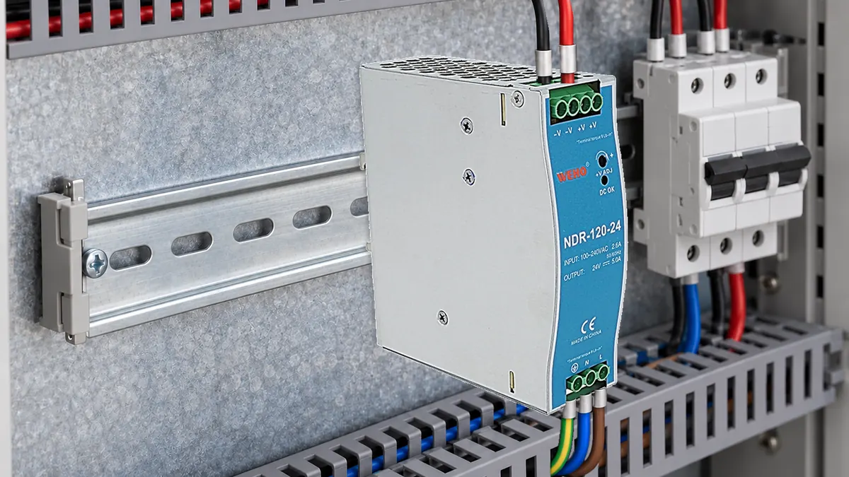
A good SPD rating can be weakened by cabinet routing
An external surge protective device (SPD) does not impose its catalog protection voltage directly on a power supply several connections away. The intervening conductors contribute voltage during a fast surge. A neat cabinet can therefore have a poor protection path when the SPD is installed across the enclosure and connected through spare cable loops.
For a cabinet using the WEHO NDR-120-24 DIN-rail supply, identify the exact power supply first. WEHO’s NDR-120 specification lists the 24 V, 5 A variant. Those output ratings do not establish its input surge immunity or prove that a particular external SPD is coordinated with it.
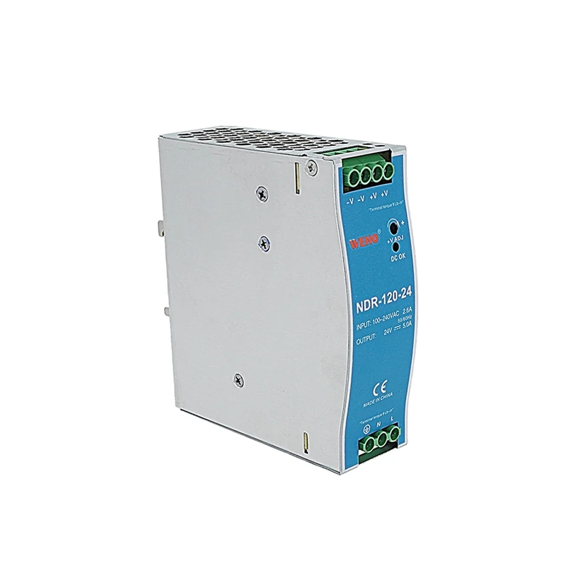
The design decision is whether the complete installed arrangement limits the relevant transient at the PSU input terminals. This article addresses connection length and routing. WEHO’s power supply surge protection overview provides the broader starting point for surge sources and protective-device categories.
Count the path that carries surge current
Lead length means electrical route length, not the air gap between the SPD housing and the power supply. For the arrangement illustrated in Schneider Electric’s installation guide, the counted path runs from the network connection, through any external short-circuit protective device and SPD, to the earthing terminal block. The guide recommends a total connection length no greater than 0.5 m for that arrangement. See its SPD cabling rules.
Define the protection mode before measuring. A line-to-neutral assessment and a line-to-protective-earth assessment do not automatically contain the same conductors. Draw the relevant connection points and identify which segments carry the surge current for each mode. A single distance written beside the enclosure cannot describe every path.
Keep the SPD connection path separate from the downstream feeder distance in the drawing. The first affects connection-induced voltage; the second can introduce additional propagation and coupling considerations. A short SPD earth lead alone cannot establish the complete installed protection level.
The 0.5 m recommendation is a layout target tied to the illustrated installation guidance, not permission to ignore the selected SPD manual. Terminal arrangement, disconnector requirements, conductor sizing, earthing system, and local installation rules still govern the actual assembly. NEMA specifically directs installers to check the manufacturer’s instructions, particularly lead length and fuse or breaker requirements.
Estimate the lead contribution before fixing the layout
A simplified screening relationship is:
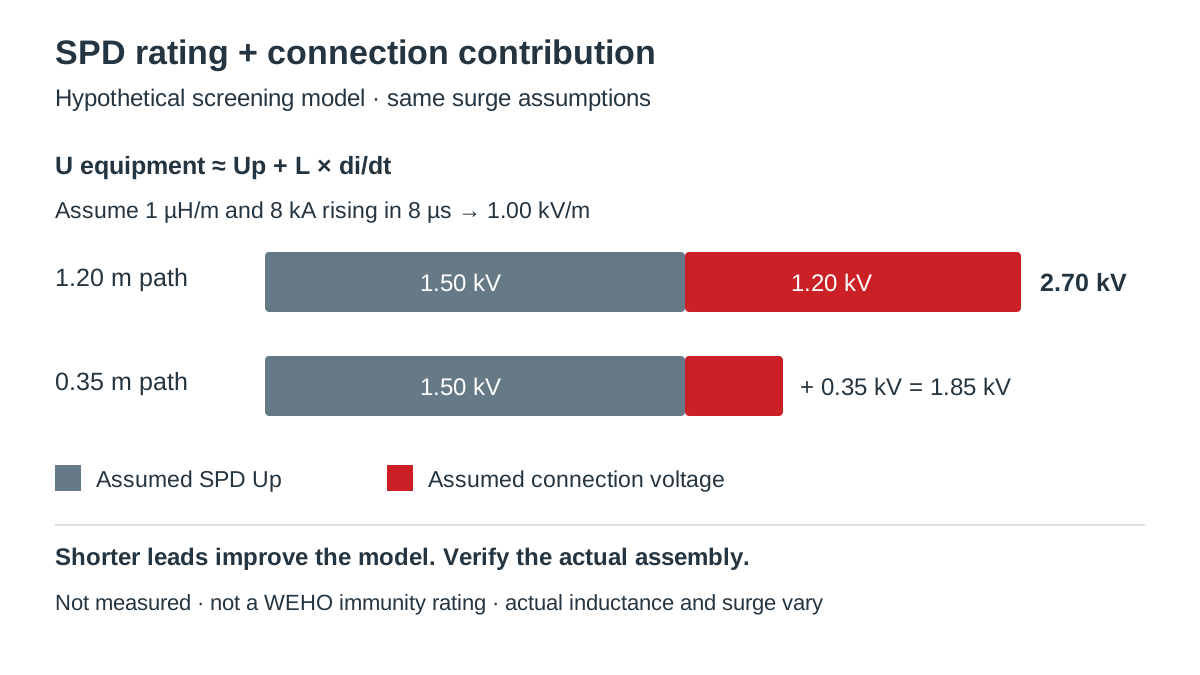
U at equipment ≈ Up + L × di/dt
Here, Up is the SPD protection level under the stated test conditions, L is the effective inductance of the relevant connection path, and di/dt is the surge-current rate of rise. The expression is a screening model; it does not include every coupling, propagation, or nonlinear effect in a complete cabinet.
Schneider Electric’s connection example uses approximately 1 µH/m and an 8 kA current rising over 8 µs to illustrate about 1,000 V of added voltage per meter. These assumptions explain why a few extra conductor loops matter. They are not a universal conversion factor for every SPD installation.
Swipe horizontally on a small screen, or open the full-size diagram.
Hypothetical cabinet layout calculation
Assume a proposed SPD has Up = 1.5 kV at the relevant declared test condition. For this calculation only, use an effective path inductance of 1 µH/m and a current rise of 8 kA in 8 µs. Compare two proposed connection paths: 1.20 m before rearrangement and 0.35 m after rearrangement.
The assumed current slope is 8,000 A ÷ 8 µs = 1,000 A/µs. The longer path gives L = 1.20 µH and an estimated lead contribution of 1.20 µH × 1,000 A/µs = 1.20 kV. The shorter path gives 0.35 µH × 1,000 A/µs = 0.35 kV.
| Screening item | Long route | Short route | Decision implication |
|---|---|---|---|
| Counted connection path | 1.20 m | 0.35 m | Move components before specifying extra cable. |
| Assumed lead contribution | 1.20 kV | 0.35 kV | Same assumed current slope and inductance per meter. |
| Up plus lead contribution | 2.70 kV | 1.85 kV | Use for screening, then verify the assembly. |
| Hypothetical 2.50 kV comparison level | Exceeds level | Below level | A numerical comparison alone does not establish immunity. |
The rearrangement reduces the modeled lead contribution by 0.85 kV. It does not turn the example into an NDR-120-24 test result. The assumed 2.50 kV comparison level belongs only to this example; it is not a WEHO specification, equipment withstand declaration, or acceptable surge-test level.
An equipment insulation withstand value and a functional surge-immunity test also answer different questions. Before accepting either layout, obtain the PSU’s applicable test modes, waveform, coupling method, levels, and performance criteria. An AC dielectric-strength figure cannot be substituted for that information.
Decide what to change in the cabinet
Shorten the connection path before treating a larger conductor as a complete remedy. NEMA explains that connecting-lead inductance adds to residual voltage and that shortening the lead has a stronger effect than a comparable practical increase in conductor size. Conductor cross-section must still satisfy the selected equipment instructions and fault-current requirements; do not reduce it merely to make routing easier.
Separate protected outgoing conductors from the incoming surge-exposed route. Schneider’s cabling guidance treats physical separation and loop-area reduction as additional measures. Bringing both routes together in the same long duct after the SPD can undermine the intended layout through coupling, even when the SPD itself sits near the incoming terminals.
| Observed condition | Proposed action | Record required | Verification basis |
|---|---|---|---|
| Long SPD branch or spare loop | Reposition SPD and connection points. | Segment lengths for each protection mode. | SPD instructions and installed protection assessment. |
| External disconnector adds a detour | Review the approved SPD/disconnector arrangement. | Exact device combination and route. | Manufacturer coordination instructions. |
| Incoming and protected routes reconverge | Revise cable segregation. | Annotated cabinet layout. | Applicable routing guidance and assembly test. |
| PSU surge information is unavailable | Obtain the relevant report or declaration. | Modes, levels, conditions, and criteria. | Exact PSU revision and project requirements. |
A second SPD near the load may be a design option, but two devices cannot simply be added as independent clamps. Their coordination, connecting network, and installation conditions need an engineering basis. Likewise, do not assume a protective-earth bond through painted mounting hardware is an approved surge-current path.
Verify the proposed installation in a defined sequence
- Identify the equipment and protection modes. Record the PSU revision, SPD part number, supply earthing arrangement, and relevant line/neutral/earth combinations. Check that the protection assessment covers the project’s actual modes.
- Measure the complete connection paths. Record individual conductor segments, external disconnectors, bends, and spare lengths on the drawing. Reconcile the totals with the actual installed routing, rather than the enclosure dimensions.
- Check coordination documents. Record the SPD’s applicable voltage rating, protection level, backup protection, and installation instructions. Verify the selected combination against the supply conditions and the equipment requirement; flag missing limits instead of inventing acceptance values.
- Inspect route separation and bonding. Record incoming versus protected cable routes and the specified bonding provisions. Verify against the selected assembly and SPD instructions before energizing the cabinet.
- Qualify the complete arrangement. Define the relevant surge tests and functional criteria with the responsible engineer or test laboratory. Record test conditions, actual assembly configuration, and results; repeat affected checks after component or routing changes.
A continuity check can confirm an electrical connection, but it does not measure the high-frequency behavior represented by the calculation. Surge qualification requires suitable equipment and competent personnel. Keep test photos and the final routing drawing together so that production does not replace a qualified short route with a convenient long one.
Prepare the power supply interface for review
For an NDR-based cabinet, use the NDR-120-24 product and document entry to identify the proposed supply. Send WEHO your interface requirements with the input system, exact PSU revision, SPD model, connection-path drawing, and required test conditions. Ask which current product documents are available for the assessment.
Engineering FAQ
Does a short earth lead guarantee protection at the PSU input?
No. The relevant protection path includes more than the SPD earth lead. Count the applicable live-side connections and external disconnector, identify the protection mode, and assess the installed voltage at the equipment terminals.
Can thicker SPD cables compensate for a long route?
Thicker conductors do not eliminate the inductive penalty of unnecessary length. Select the required cross-section from the applicable instructions and fault conditions, then keep the permitted connection route short and direct.
Is the SPD’s Up the voltage the PSU will always see?
No. Up describes the SPD under specified conditions; connecting conductors and the rest of the installation affect equipment-terminal voltage. Use matching test conditions and a complete installation assessment before comparing protection with equipment requirements.
Can an ordinary continuity test validate the surge path?
No. A continuity test does not establish transient inductance or functional surge immunity. It is one inspection input; the assembly still needs the documentation, routing checks, and qualification appropriate to the project.



