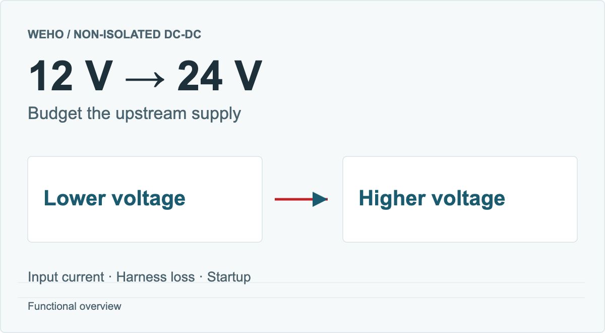
Choose a common-negative DC-DC converter when the source and load can share an electrical reference and all connected interfaces meet their reference-voltage and functional-error limits. Plan the power return and external signal paths before installation. In this arrangement, input negative and output negative belong to the same conductive network; the module does not create a separate floating reference.
Start with a connection drawing that includes every cable. A converter can produce the expected voltage at its own leads while a shared return shifts the reference seen by an external input. The result may be an offset, communication errors or current in a cable intended only for signaling. Converter selection alone does not settle that system question.
Article sections
Map the power return and every external connection
Give each reference a physical name: source negative, converter common junction, load return, controller signal common and chassis. Do not replace them all with an identical ground symbol before their relationships are defined. A black power lead identifies the documented connection; it does not establish protective earth, chassis bonding or an isolated interface.
| Connection | Question for the drawing | Evidence to retain |
|---|---|---|
| Source and load negatives | Which conductor and connector carry each power current? | Harness routing, conductor size and connection points |
| Controller signal common | Does it join the load return at one point or provide another conductive route? | Interface schematic and permitted reference difference |
| Cable shield and chassis | Where are shield, connector shell and chassis actually connected? | Equipment bonding and EMC design |
| Service or test connection | Does the attached instrument add a connection to another reference? | Instrument input arrangement and connection procedure |
List normal operation, a powered controller with an unpowered load, maintenance connections and permitted disconnections. The drawing should still explain the current path in each state. A signal cable must not become an accidental substitute for a disconnected power return. If the equipment uses external input-polarity protection, review its boundary and connected return paths alongside this grounding drawing.
Calculate the reference shift in a shared segment
Consider a hypothetical low-frequency example. A 4 A load returns through an external conductor segment with 20 mΩ resistance to a common junction. The controller references that junction, while a single-ended signal is generated relative to the load-side end of the segment. Initially assume the signal input adds negligible return current and there is no parallel conductive path.
| Quantidade | Assumption or calculation | Result |
|---|---|---|
| Load current through the defined segment | 4 A | 4 A |
| Segment resistance | 20 mΩ = 0.020 Ω | 0.020 Ω |
| Reference difference | ΔV = I × R = 4 × 0.020 | 0.080 V = 80 mV |
| Signal error contribution | 80 mV ÷ a hypothetical 5 V signal span | 1.6% of span before other errors |
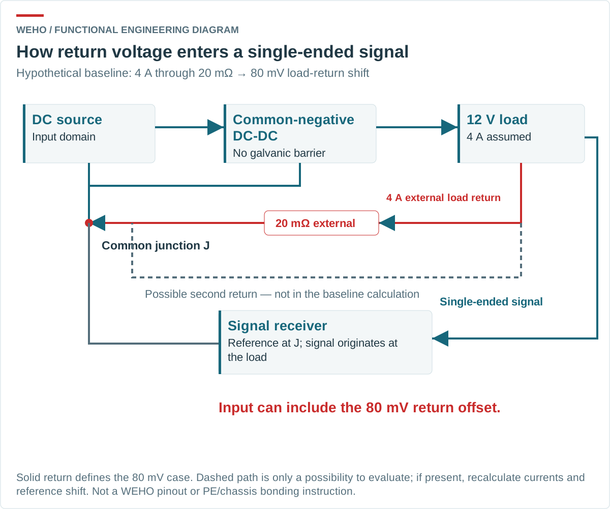
The 80 mV is a calculated reference difference, not measured converter ripple. Whether it is acceptable depends on the actual receiver. It is neither a universal communication limit nor a claim that every signal sees the full error.
The 4 A belongs to the specified external load-return segment. It must not be assigned automatically to every black wire in a three-terminal buck arrangement. Currents at other junctions follow the complete input and output network. Once another return path is connected, determine current division from its impedance; the original single-path calculation no longer describes the whole system.
Use the WH-C241210 connection identity correctly
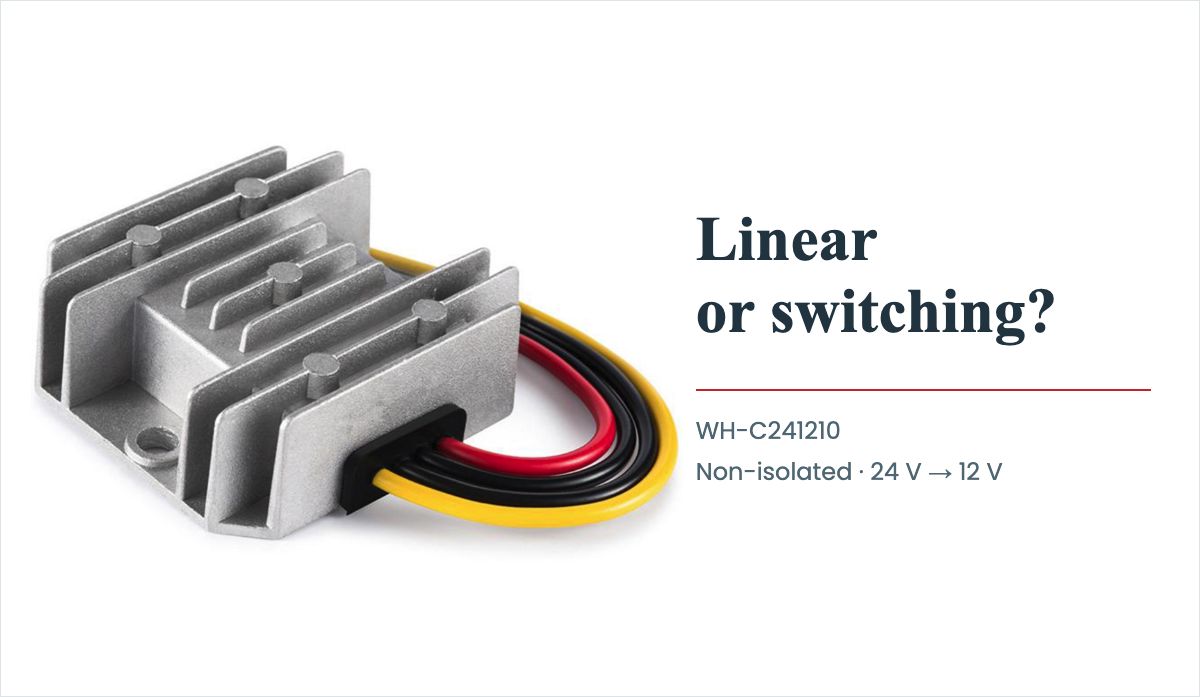
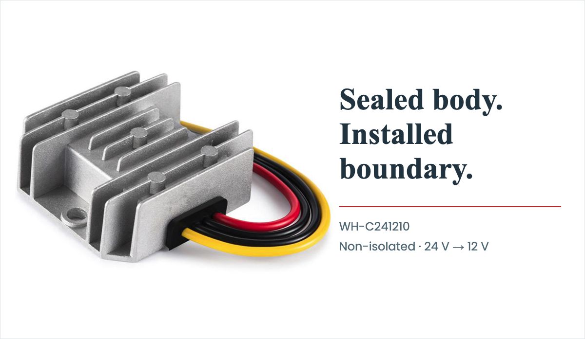
The WEHO WH-C241210 product details e WH-C241210 specification identify a non-isolated module with red input positive, black input/output common negative and yellow output positive. That shared negative is the relevant product fact for this review.
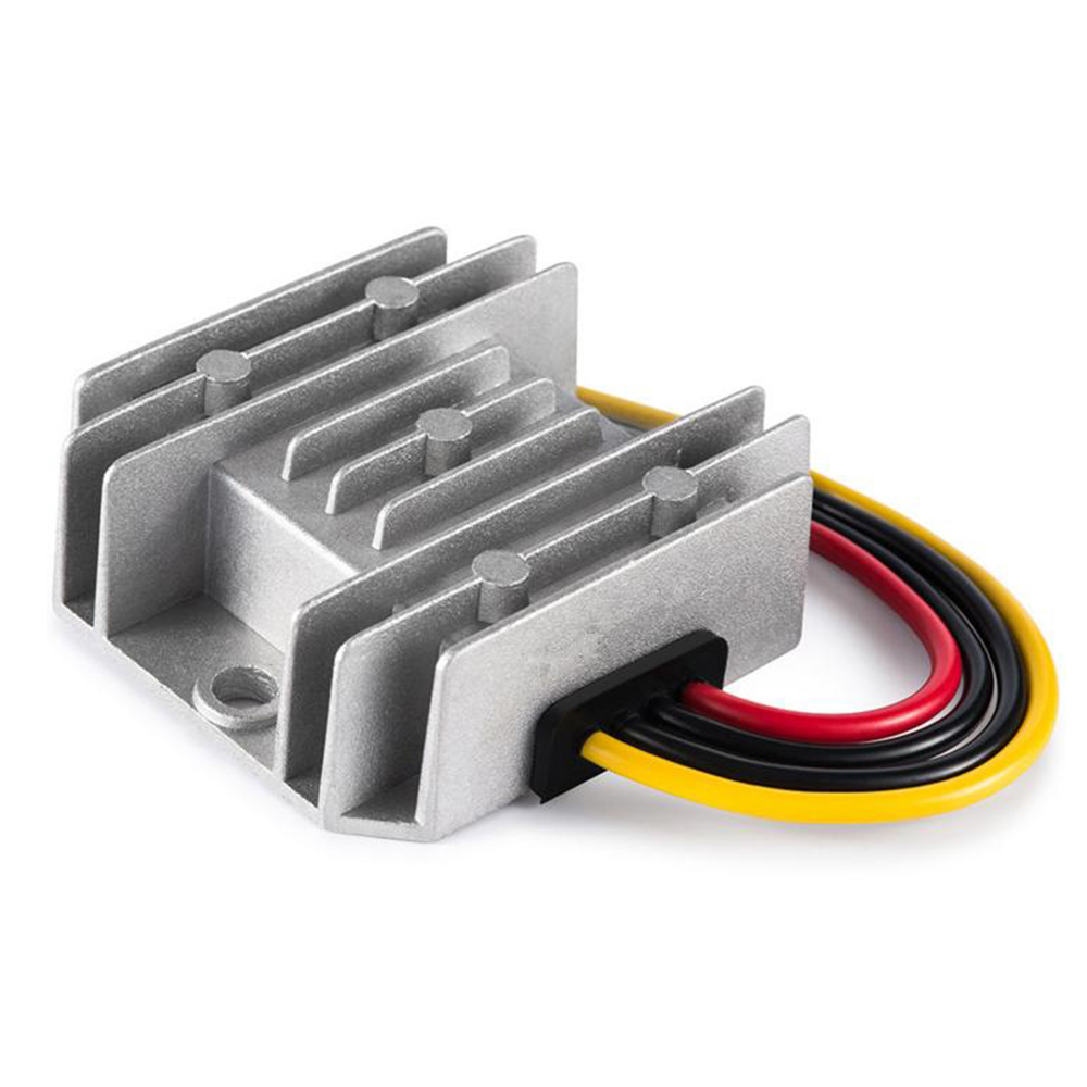
The photograph identifies the product appearance; it does not approve a particular chassis bond or signal connection. For an OEM harness, obtain the applicable model revision and release a connector drawing that names each function. Confirm the source polarity and voltage at the intended input before connecting the load.
Choose an interface arrangement that controls current
A useful first change is often to route a sensitive reference separately from the conductor carrying a large load current, joining it at the intended reference point. This reduces shared resistance only if the physical routing delivers that separation. Adding another wire without tracing its connections can instead create a loop.
| Approach to evaluate | What it can address | What still needs checking |
|---|---|---|
| Separate sensitive and power return routing | Voltage developed across a deliberately shared conductor | Actual junction location, connector resistance and high-frequency paths |
| Differential interface | Dependence on a single-ended ground reference | Receiver common-mode range, cable arrangement and protection |
| A specified isolated signal or power boundary | An unwanted conductive route between separate references | The complete barrier, including other cables, shields and auxiliary supplies |
Analog Devices explains the shared-impedance problem in Staying Well Grounded and the effect of multiple conductive connections in its ground-loop isolation discussion. These are reasons to analyze the connected system, rather than prescribe one grounding pattern for every frequency and interface. A non-isolated converter does not itself supply a galvanic barrier.
Verify the assembled system in its real operating states
Measure voltage between named reference points while changing the representative load. Record the connection state, current, source setting, cable arrangement and instrument bandwidth. Use a measurement arrangement appropriate to the common-mode voltage; an instrument ground connection can change the circuit being evaluated.
Check the signal or communication function at the same time. A stable DC reading does not establish that a fast load change is acceptable. Conversely, a visible transient is not automatically a functional failure: compare it with a defined receiver limit and the required equipment behavior.
Evaluate permitted service connections as separate configurations. If the power return can be opened during normal maintenance, define a procedure or interlock that prevents an unintended signal-current path. Do not remove a required protective-earth connection to make an electrical symptom disappear.
Release a return-path requirement with the converter inquiry
The design record should identify the intended common junction, conductors carrying power, permitted reference differences, interface limits and the configurations used for acceptance. This makes a later harness or controller substitution reviewable.
Include the largest calculated or measured difference between named references and the receiver’s permitted common-mode range and signal-error budget. If return routing cannot meet those limits, evaluate a suitable differential interface or a properly specified isolation boundary. An isolated power converter alone may leave a conductive connection through another signal cable, shield or auxiliary supply; review the complete connected system before changing topology.
Send WEHO the common-negative converter and interface requirement with the source range, output load, connection drawing, external interfaces and intended mounting. Ask for the exact model and applicable connection documentation. If the project needs separate electrical references, state that before selecting a non-isolated module.