Reverse polarity protection for a non-isolated DC-DC converter must be specified at the input assembly level. Define the reversed voltage, connection duration, available fault energy, connected return paths, and acceptable normal-operation loss. Then verify the complete protection arrangement against those conditions. A converter’s correct input-voltage range does not establish that it survives a backward connection.
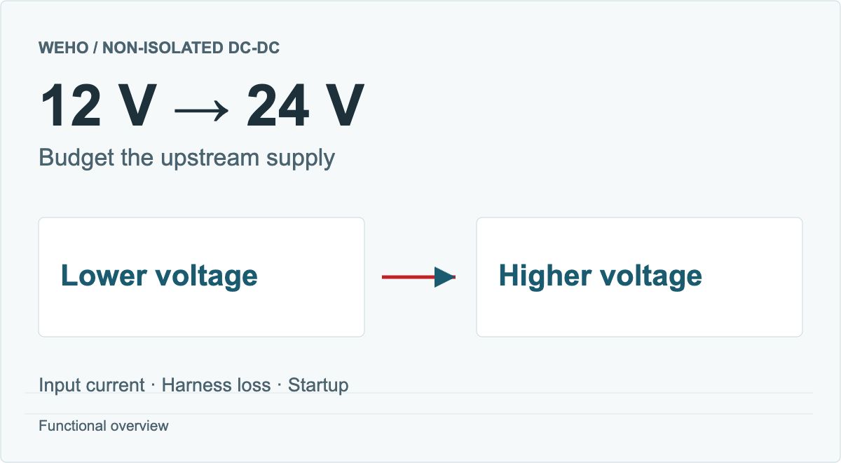
For an OEM using a nominal 24 V distribution system and a 12 V converter, the useful output is a reviewable interface requirement: what the protected assembly must tolerate and what voltage must still reach the converter. Choosing a familiar diode or a module advertised as reverse protected is only part of that task.
Article sections
Define the reversed-input event and its return path
A reversed input means the supply polarity at the equipment connection is opposite to the intended polarity. Reverse current is a different event: energy flows backward while the terminal polarity may remain correct. A circuit that addresses one condition need not address the other. TI discusses that distinction explicitly in Basics of Ideal Diodes, section 5.
Start with the assembly boundary. Record whether a reversal can occur at a battery connector, field terminal, interchangeable harness, or service connection. Specify whether the event is a brief contact or a sustained connection. An unspecified duration leaves both electrical stress and the expected recovery behavior unclear.
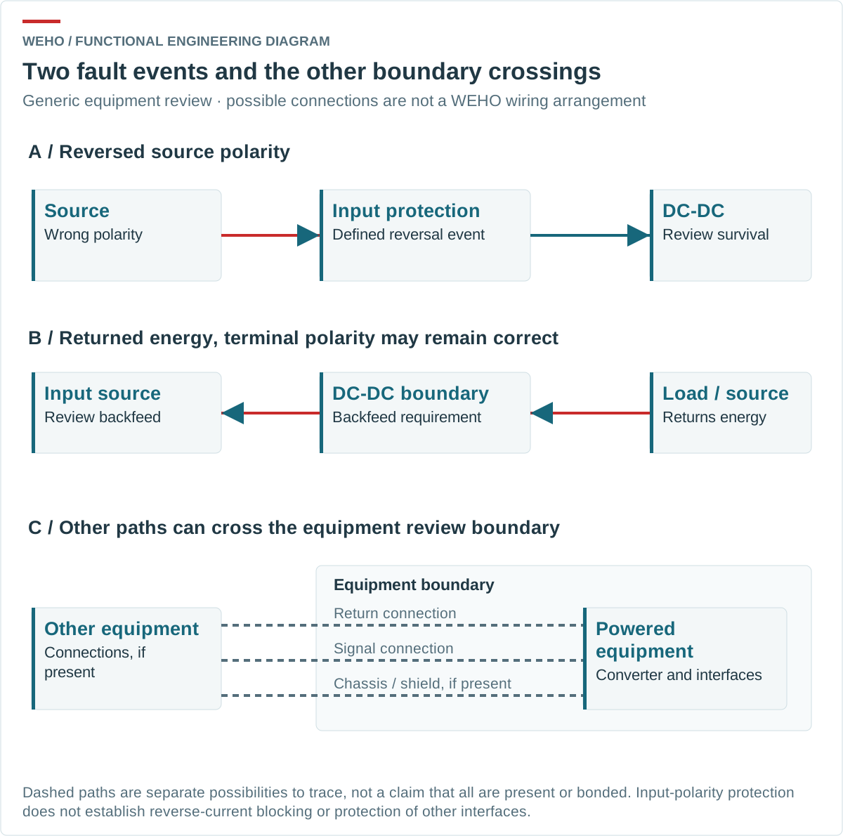
Include every intentional connection crossing the boundary: supply return, chassis connection, communication cable, shield, and any separately powered load. A non-isolated converter does not introduce a galvanic isolation barrier between its input and output. Moving its return potential can therefore affect other connected equipment. Use the non-isolated shared-return review to map those paths. The acceptance drawing must show them even when the protection is represented only as a functional block.
Compare protection approaches using the same requirements
TI’s Reverse Current/Battery Protection Circuits describes series-diode and MOSFET approaches, including high-side and return-path arrangements. Their normal-operation losses differ. Device orientation, control, and voltage ratings still require a design review; the table below is a comparison framework, not a complete circuit.
| Approach | Normal-operation question | Boundary question to resolve |
|---|---|---|
| Series blocking diode | How much voltage and power are lost at the actual current and temperature? | Is its reverse-voltage capability adequate for the defined event? |
| High-side MOSFET arrangement | What resistance and controller losses apply under the specified conditions? | Does the complete arrangement provide the required input-reversal behavior and, separately, any required reverse-current blocking? |
| Return-path MOSFET arrangement | What voltage develops across the switching element? | Can other returns bypass it or create an unacceptable reference shift? |
| Purchased protection assembly | What are its loss, thermal, and startup limits? | Which exact faults, polarities, wiring states, and revisions were tested? |
A MOSFET body diode and an enhanced channel provide different conduction paths. An enabled channel can conduct in either direction. TI’s illustrated simple reverse-battery arrangements therefore do not, by themselves, establish blocking of output-driven current at correct polarity. The outcome depends on orientation, gate control and the complete switching arrangement; verify the required behavior rather than generalize from a single-MOSFET label.
Do not use “MOSFET protected” as a substitute for those answers. Similarly, a fuse specification by itself does not document how the downstream converter behaves during reversed input. Protection functions and fault coordination need separate evidence.
Calculate the normal-operation voltage loss
Hypothetical comparison: a protection assembly is reviewed at a fixed 4 A input current, with 18.50 V at the upstream source and 0.10 Ω total harness-loop resistance. Candidate A has an assumed 0.45 V forward drop. Candidate B has an assumed effective 0.020 Ω conducting resistance. These are illustration inputs, not specifications for a WEHO converter or a selected protection device.
The harness drop is I × R = 4 A × 0.10 Ω = 0.40 V. For A, converter-terminal voltage is 18.50 − 0.40 − 0.45 = 17.65 V, and the blocking element dissipates 0.45 × 4 = 1.80 W. For B, its drop is 4 × 0.020 = 0.08 V, leaving 18.02 V; conduction loss is 4² × 0.020 = 0.32 W.
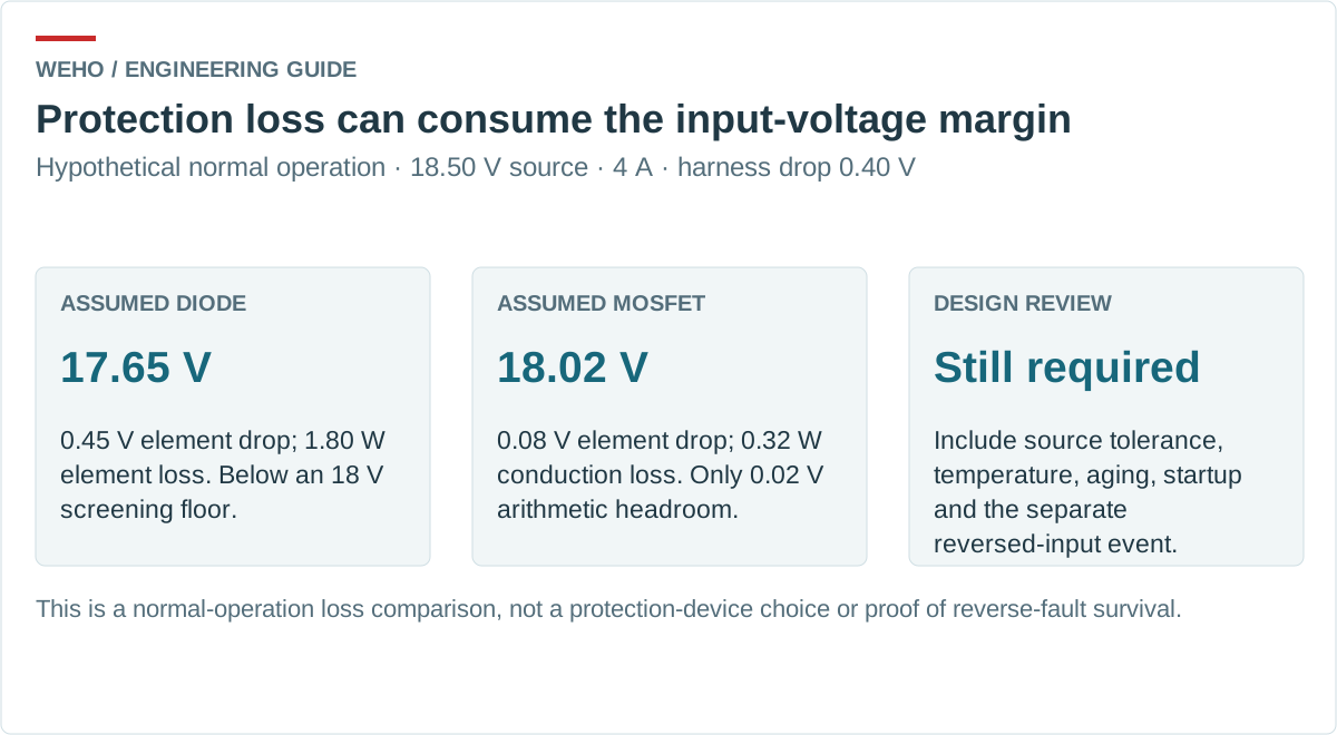
Against an 18 V screening floor, A is below the floor and B has only 0.02 V of arithmetic headroom. B therefore does not establish a robust design. Source tolerance, connector aging, current changes, temperature-dependent resistance, startup behavior, and converter input requirements remain to be checked. The calculation isolates the normal-operation loss tradeoff; it does not predict a reverse-fault response.
Review the WH-C241210 documentation separately
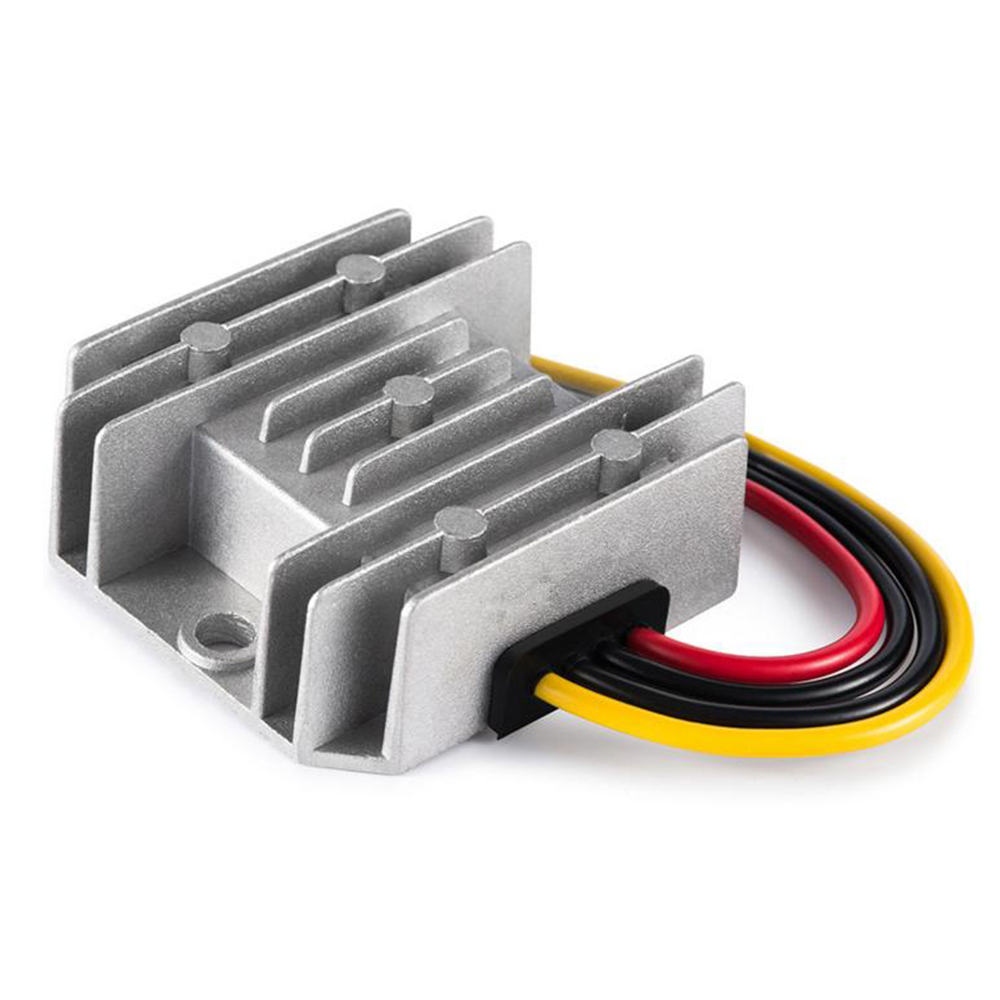
The WEHO WH-C241210 product detail and its model specification identify a non-isolated, common-negative converter with an 18–32 V input range and a 12 V, 10 A, 120 W nominal output. The specification also lists 18 V startup at 100% load. That makes voltage lost before the converter relevant to a candidate review.
The earlier 4 A illustration is not a full-load startup calculation. Even an ideal, lossless 120 W conversion would require 120 ÷ 18 = 6.67 A of steady input current at an 18 V converter boundary; real conversion loss raises that steady requirement. Thus a fixed 4 A illustration cannot approve full-load operation. It also does not establish startup inrush or prove that a particular unit will fail to start. The actual source, current waveform, temperature-dependent protection resistance and converter-terminal voltage must be assessed together. Use a defined DC power and loss boundary for steady measurements.
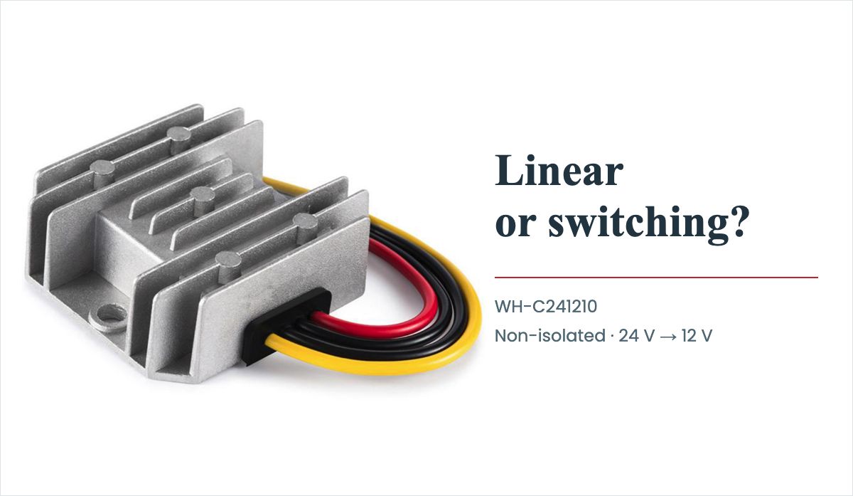
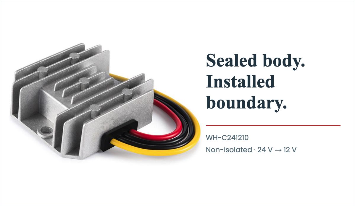
The reviewed documents do not establish a reverse-input-polarity rating. Do not assume that overcurrent protection, automatic recovery, a sealed body, or the appearance of the leads provides that function. Request the applicable controlled revision and the input-reversal evidence for the supplied assembly. A product photograph identifies the reference appearance; it cannot show the internal protection or demonstrate fault survival.
Define a controlled acceptance matrix
Agree the test conditions and pass criteria before sample evaluation. Use a reviewed laboratory procedure with suitable source limits and instrumentation; this article does not prescribe deliberately reversing an unprotected converter.
| Condition | What the record must identify | Decision criterion |
|---|---|---|
| Correct polarity, lowest required source voltage | Load state, harness, temperature, converter-terminal voltage | The equipment starts and operates within its agreed limits |
| Correct polarity, highest continuous current | Protection loss and temperature at defined measurement points | The reviewed electrical and thermal limits are met |
| Defined input reversal | Magnitude, duration, source capability, connected returns | Required blocking or survival behavior is documented without prohibited damage |
| Restoration of correct polarity | Reset sequence, output state, restart conditions | Recovery matches the equipment requirement |
| Output backfeed, if relevant | Correct terminal polarity with a separate energy source at the load | Assessed as a distinct reverse-current requirement |
A satisfactory result applies to the recorded configuration. Changing the protection device, harness, grounding scheme, or connected interface can change the boundary and requires a change-impact review.
Request a defined input-interface review
Send WEHO your non-isolated converter input-interface requirements, including:
- Source range, required output and steady/startup load conditions.
- Harness drop, connected returns, protection arrangement and permitted normal-operation loss.
- Reversed-input magnitude/duration and any separate output-backfeed requirement.
- Temperature conditions, required recovery and the evidence needed for the exact assembly revision.
Ask which exact converter and protection configuration can be reviewed against that document.
Keep the result attached to the full model, applicable specification revision, harness definition, and acceptance record. That gives purchasing and engineering the same interface to compare, rather than treating a broad protection label as proof of suitability.