LED driver soft start and lighting fade-in describe different parts of a turn-on event. A driver may control how its electrical output starts, while a lighting controller changes the requested light level over time. Specify the event, electrical response and optical result separately before accepting a “smooth start” claim.
For a luminaire OEM, the decision is whether the complete assembly turns on within the required delay and brightness trajectory. A compatible dimming interface or an acceptable steady-state output does not answer that timing question.
On this page
Identify three events instead of one startup time
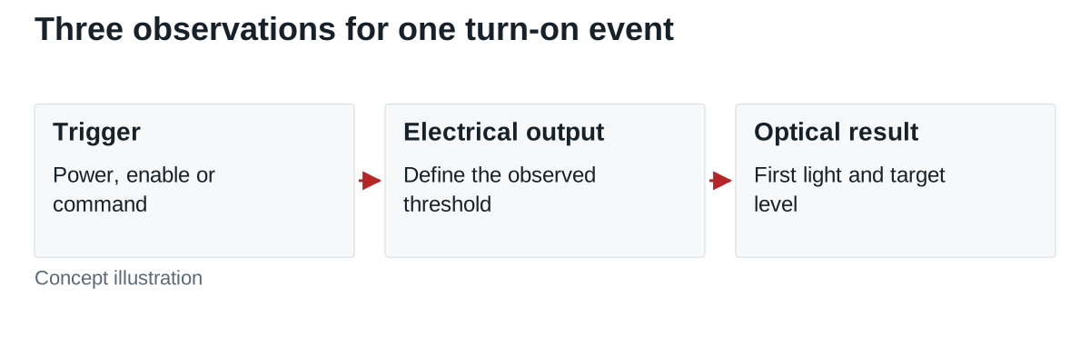
Start with the command or power event: AC energization, a documented enable input, or a dimming command while the driver remains powered. Then identify electrical output behavior at the LED assembly. Finally, define what counts as visible light and the target optical level.
Those events can have different delays and ramps. Texas Instruments’ LM3410 information identifies soft start and PWM dimming as distinct device features. That is a device-level example; it does not establish the timing or circuitry inside a WEHO driver.
Lutron’s Maestro programming guide describes fade-on time as the controller’s progression toward a desired light level. Its settings are specific to that dimmer. The useful general distinction is between a commanded lighting transition and a power stage’s startup behavior.
Write observable requirements
| Requirement | Define before testing | Preserve with the result |
|---|---|---|
| Trigger | AC application, enable assertion or a particular control command | Signal reference, initial state and timestamp definition |
| First output | Electrical threshold at the relevant LED connection | Current/voltage capture and measurement position |
| First light | Optical threshold, detector arrangement and observation conditions | Optical capture and common time reference |
| Fade trajectory | Initial/target level, timing markers and permitted discontinuities | Controller setting, driver and LED configuration |
| Final condition | Allowed electrical and optical settling behavior | Defined limits and pass/fail result |
| Repetition | Required cold, warm, standby or interruption cases | Input, temperature, off-time and sequence details |
A requirement such as “reach the target in one second” is incomplete until its starting event and endpoint are defined. One team may start the clock at AC application, another at the controller’s command, and another at first light. They can report different results from the same assembly without any measurement error.
Read a timing record without merging its intervals
Hypothetical acceptance example: a project starts its clock at AC application. It requires first light by 0.40 s and the agreed target optical level by 1.80 s. A separate requirement specifies a 1.00 s interval between first light and that target. These are invented project limits, not a lighting standard or WEHO performance values.
Assume a fictional record shows first electrical output at 0.25 s, first light at 0.30 s, and the target optical level at 1.30 s. The first-light delay is 0.30 s; the fade interval is 1.30 − 0.30 = 1.00 s; total time to target is 1.30 s. Those assumed markers meet the three stated timing requirements.
Now suppose first light instead occurs at 0.70 s and the target at 1.70 s. The fade interval remains 1.00 s and time to target remains below 1.80 s, but first-light delay fails the 0.40 s requirement. Calling both records “one-second fade-in” conceals the difference that matters to the project.
These numbers are a comparison of timestamps, not simulated or measured driver waveforms. They do not define acceptable overshoot, visual smoothness, color consistency or flicker. Add those requirements only where the equipment specification calls for them, with appropriate observation methods.
Test the actual ways the luminaire turns on
Separate a cold AC start from a command sent to an already energized driver. Also consider the relevant warm restart, standby exit, restoration after an input interruption and the retained last-level or default-level behavior. Use the events the equipment will actually encounter rather than an arbitrary universal test cycle.
Keep controller settings and firmware with the driver model, suffix, LED assembly and input conditions. If the startup state depends on retained settings, record how those settings are initialized. A replacement controller or a software change can alter the observed light transition even when the power supply is unchanged.
Electrical current can help explain an optical result, but it should not silently replace a required optical measurement. Fix the detector geometry and relevant environment for repeated optical comparisons. If multiple channels must appear together, observe the channels against the same event rather than combining unrelated captures.
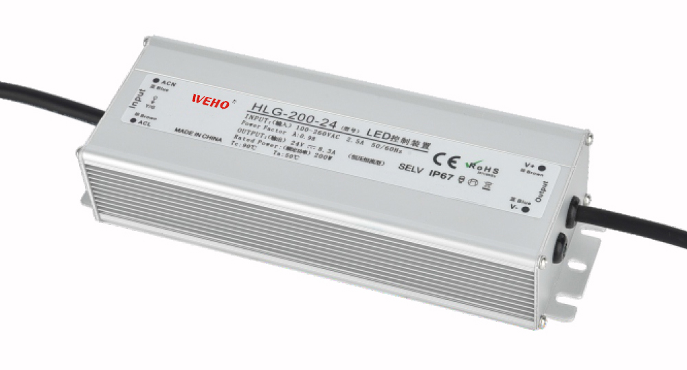
For a document-reading example, the public WEHO HLG-200 specification includes a 30 ms rise-time entry in its setup/rise/hold-up row at 230 VAC and full load. The photographed variant is WEHO HLG-200-24. Keep the setup delay after AC energization separate from the output rise interval when interpreting that row. That electrical timing entry does not specify the luminaire’s optical first-light time, an adjustable fade-in function or its response to a particular lighting controller. Use the applicable electrical entry as one input to a turn-on record, then obtain the missing optical and control evidence for the actual driver, LED assembly and event.

Do not use a gentle light transition to prove AC inrush control
The initial charging of an AC input and the later LED-output ramp are different events. A driver can present a gradual light rise while its input still imposes a significant switching duty on the upstream device. Use the exact input-inrush data and installation conditions for breaker, relay and contactor review.
Likewise, soft start does not mean that LED hot connection is permitted, that an output can be disconnected under load, or that every controller fade command will be followed. Those are separate model-level interface and operating questions.
Request the turn-on evidence your project needs
Send WEHO the proposed driver model, LED load, control interface, triggering event, required first-light and target-level timing, repetition cases and optical/electrical limits. Ask for applicable model information and identify which complete-luminaire observations still need to be made.