



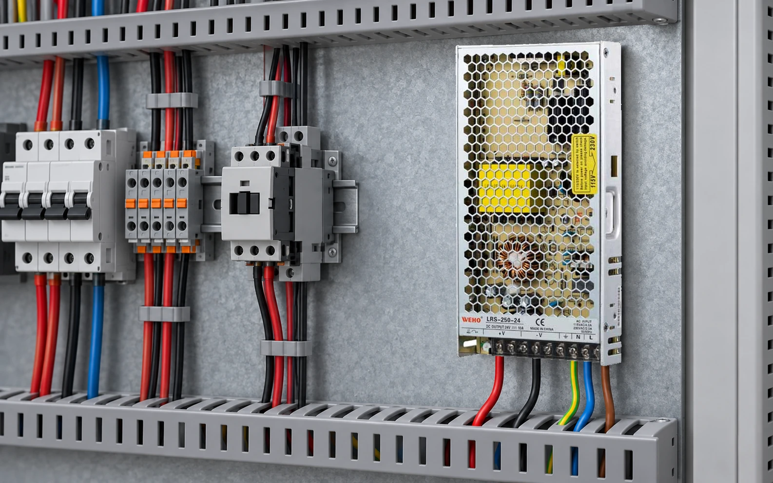
Several screws marked +V and −V on a single-output supply are not evidence of several independently rated power rails. Review the applicable terminal assignment, total output limit and each external branch. Do not multiply the supply’s rating by the number of screw positions.
This guide is for a panel designer creating a distribution record around the LRS-250-24. Its useful output is a traceable branch map that keeps the supply limit separate from terminal and conductor limits.
Read the exact terminal assignment first
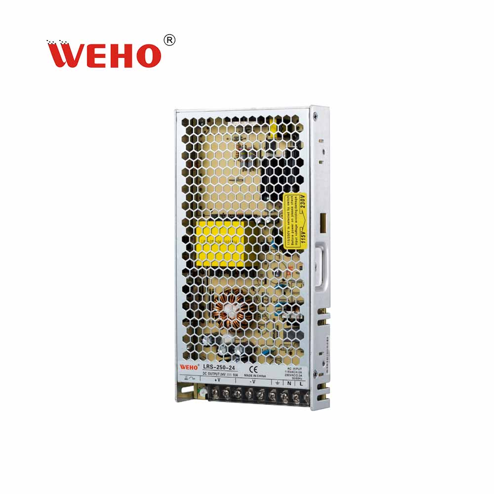
The LRS-250 page identifies this as a single-output family, and the 24 V table column lists a 0–10 A range. The original photograph has repeated DC markings and separate input markings. Read the drawing for the supplied revision before assigning a conductor; do not infer electrical independence from spacing.
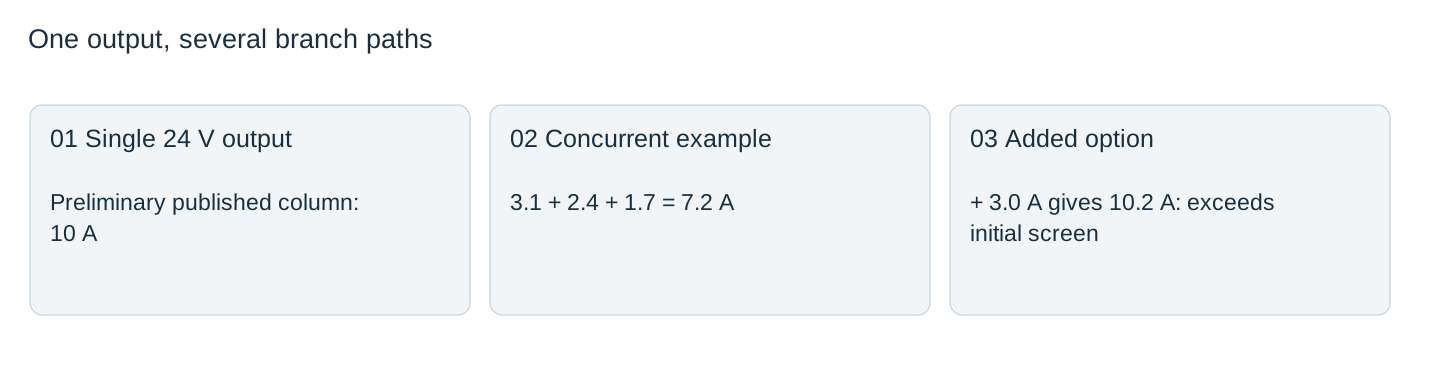
The “250” family name and a 24 V × 10 A arithmetic product must also not be treated as interchangeable guaranteed continuous output conditions. For this review, the published 10 A column is the preliminary current ceiling; the supplier must establish the applicable operating conditions and revision.
Add the currents that can actually run together
For a hypothetical concurrent state, Branch A draws 3.1 A, B draws 2.4 A and C draws 1.7 A. The sum is 7.2 A. At a nominal 24 V that is 172.8 W. Moving Branch C to another +V screw does not reduce the 7.2 A demanded from the source.
Adding a 3.0 A option raises the simultaneous sum to 10.2 A. This exceeds a 10 A initial screen even if no individual branch draws that much. The diagram is a functional distribution map, not permission to land these loads directly on the supply.

Check local paths without inventing a per-screw rating
| Limit | What establishes it | What does not establish it |
|---|---|---|
| Supply total | Exact variant and operating conditions | Number of +V screws |
| Terminal connection | Applicable terminal instructions and allowed conductors | One third of the total rating by assumption |
| Branch conductor | Installation, current and protective coordination | Supply model name alone |
| Shared return | Total return current through its actual path | Positive-wire labels only |
The available product table does not provide a complete external terminal-use approval for every possible conductor combination. Do not assign “5 A per screw,” double-lug a position or bridge screws simply to use all available holes. Obtain the terminal instructions and use suitable distribution hardware where required.
Trace the return path with the same care as the positive path
A drawing that shows only positive branches is incomplete. Record which return conductor carries each load current, where returns join and whether a connector carries combined return current. A small return path can carry more than a single branch even when the positive conductors look well divided.
PE, chassis bonds and DC negative perform different functions. Repeated −V access does not authorize using PE as a return or adding an arbitrary bond. Keep any grounding decision separate and supported by the equipment design.
Release a branch map that survives field changes
Label each branch by receiver and conductor identification, not only by a terminal number. Record simultaneous states, the evidence behind each demand and which options are mutually exclusive. If software later allows two options to run together, reopen the sum.
During the authorized assembly test, verify receiver voltage under the demanding state and inspect connections using the documented installation method. A correctly added current budget is an initial design check, not evidence of acceptable contact temperature or fault coordination. Preserve the final terminal assignment and actual test record with the BOM.
Send the LRS-250-24 distribution proposal with a terminal map, simultaneous branch-current schedule, conductor and lug details, and protective-device arrangement. Request the offered revision’s shared-output limits and termination instructions before releasing either the total load budget or an individual connection.
Single-output branch and return record
| State / receiver | Positive path | Return path | Current and source | Decisão |
|---|---|---|---|---|
Blank project worksheet. Enter verified project data; example calculations above are not measurements.



