



- Zero an AC/DC current probe under its specified no-current conditions before interpreting a small DC reading.
- Degaussing addresses residual core magnetization; offset adjustment addresses the remaining measurement zero.
- Bracket a low-load measurement with zero checks and compare the error allowance with the current being measured.
- A branch-current result is not an AC input standby-power measurement or a WEHO product performance claim.
Why an idle-current reading can look larger than the load
A control branch appears to draw 16 mA after its main load enters an idle state. Before changing the power supply or declaring excessive consumption, establish how much of the displayed current belongs to the probe and instrument zero. A few milliamperes of offset can dominate a small reading even when the same setup looks satisfactory at several amperes.
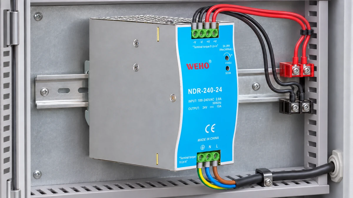
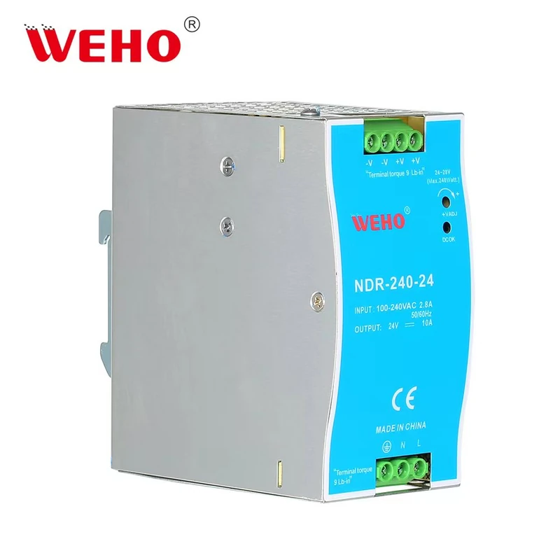
The WEHO NDR-240-24 product reference provides the supply context for this measurement plan. The procedure concerns a particular output branch and the selected instruments; it does not establish the supply's own no-load input consumption. Keep those two purchasing questions on separate test records.
Define the current and measurement boundary first
Identify whether the required value is average DC current, RMS current, a startup peak or energy over a complete machine cycle. A scope trace, a meter average and a peak detector can report different quantities from the same changing load. State the averaging interval and instrument bandwidth before comparing readings with an acceptance limit.
Define the conductor crossing the probe aperture on a simple distribution drawing. A probe enclosing both outgoing and return conductors can substantially cancel their magnetic contributions, so the reading no longer represents the current in one conductor. Changes in branch routing must be recorded because they can change what the probe actually includes.
Check the whole measurement chain: sensor type, compatible amplifier or interface, current range, conversion factor, coupling and displayed units. An AC-only probe cannot establish a DC average simply because its connector fits the oscilloscope. HIOKI's current-probe guide distinguishes AC measurement methods from arrangements that also respond to DC.
Separate degaussing from offset adjustment
Degaussing and zero adjustment solve related but different problems. The Tektronix TCP202 instruction manual explains that residual magnetization shifts the probe zero, while balancing compensates for remaining DC offset after degaussing. Those instructions describe that probe, rather than a universal button sequence for every current sensor.
Use the warm-up, range-setting, jaw position and no-current conditions required by the actual probe and instrument manuals. Some systems combine operations; others require separate sensor and instrument adjustments. An instrument's relative display function must not be assumed to demagnetize the sensor or satisfy the sensor manufacturer's preparation instructions.
Prepare the zero reference without removing the real current mathematically. Zeroing while the branch carries its idle current can subtract the quantity the test is meant to measure. Follow the probe's approved preparation method, and do not run a degauss operation around an energized conductor or susceptible circuit without explicit applicable instructions.
Record events that invalidate the previous preparation, including an overload, range change or major temperature change when relevant to the selected equipment. A new trace should carry a new preparation record when those conditions occur. A stored screenshot of a previously centered trace is insufficient evidence of the present zero.
Work a hypothetical low-current error budget
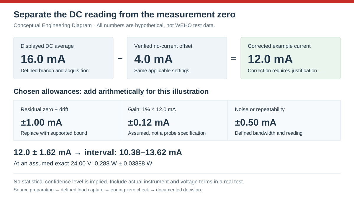
Assume a controlled example with a 24.00 V output branch, a DC average reading of 16.0 mA and a measured no-current offset of +4.0 mA under the same settings. Assume the offset correction is applicable and the branch voltage is exact for this illustration. These values are hypothetical, not measurements of an NDR-240-24 or specifications of a named probe.
The corrected current is I = I_display − I_offset = 16.0 − 4.0 = 12.0 mA. Using the uncorrected reading would overstate this example by 4.0 ÷ 12.0 × 100 = 33.3%. That percentage describes the assumed readings only; it is not a typical offset error for industrial current probes.
Now assign independent engineering allowances of ±1.0 mA for residual zero and drift, ±1% of the corrected reading for gain, and ±0.5 mA for the selected reading's noise or repeatability contribution. The 1% term is 0.12 mA. A conservative arithmetic sum is ±(1.0 + 0.12 + 0.5) = ±1.62 mA.
| Contribution | Hypothetical input | Current allowance | Evidence needed in a real test |
|---|---|---|---|
| Residual zero and drift | Chosen bound after preparation | ±1.00 mA | Applicable accuracy terms and bracketing zero checks |
| Gain | 1% × 12.0 mA | ±0.12 mA | Actual range, temperature and calibration conditions |
| Noise or repeatability | Chosen reading allowance | ±0.50 mA | Defined bandwidth, acquisition and repeats |
| Arithmetic bound | Sum of three allowances | ±1.62 mA | Confirm omitted terms and avoid double counting |
The example therefore spans 10.38–13.62 mA, or 12.0 mA ±13.5%. At the assumed exact 24.00 V, nominal branch power is 0.288 W and the corresponding current-derived power allowance is ±0.03888 W. A real power budget must also include voltage uncertainty and any correlation or time alignment relevant to the measurement.
This arithmetic bound is not a statistical confidence interval or a complete calibration uncertainty statement. Replace the assumed allowances with the actual instrument specification and a justified treatment of overlapping terms. Do not count the same offset or noise effect twice merely because two documents describe it differently.
Swipe horizontally on a small screen, or open the full-size diagram.
Decide whether the instrument can resolve the decision
Compare the measurement allowance with the project limit before collecting a large data set. For an illustrative 13.0 mA upper limit, the example's 13.62 mA upper bound prevents a clear pass under a rule requiring the whole interval below the limit. A lower-noise trace alone would not remove the dominant residual-zero allowance.
Resolution and accuracy require separate checks. Rohde & Schwarz's device power-consumption guide distinguishes measurement granularity from readback accuracy. Additional displayed digits do not independently prove that the low-current decision is supported.
An alternative instrument or calibrated shunt may improve the decision, but its insertion effects must be assessed. A series ammeter or shunt adds burden voltage and can change the branch operating point, while range switching may disturb a dynamic load. Compare methods under a controlled load state rather than assuming disagreement identifies a defective supply.
Build a repeatable preparation and capture sequence
- Define the branch and quantity. Mark the single conductor, polarity, load state, averaging time and intended limit. Record the drawing revision and acceptance rule; accept the plan when another reviewer can identify exactly which current is included.
- Prepare the actual measurement chain. Apply the equipment-specific warm-up, range, degauss and zero instructions under verified no-current conditions. Record equipment IDs and settings; proceed when preparation completes normally and the reference reading meets the chosen zero allowance.
- Capture the defined operating state. Restore the controlled test configuration and acquire the agreed interval after the stated settling condition. Save the raw record and machine-state evidence; accept the capture when the acquisition contains the complete required state without overload indications.
- Repeat the no-current check. Return to the approved reference condition using the planned isolation method. Record the ending offset and elapsed time; investigate when the drift exceeds the bound used in the calculation.
- Apply the decision rule. Correct only justified systematic terms and calculate the remaining allowance. Keep the raw reading, correction and final interval together; release a pass only when the agreed rule supports it.
These steps form a test plan for qualified personnel using the selected equipment instructions. The cabinet illustration shows product context, not a current-probe installation or a completed test. A change to the energized assembly requires its own approved work method and must not be inferred from the image.
Save a record that separates load behavior from zero drift
Retain the probe model and serial number, instrument firmware, calibration status, range, bandwidth, coupling, conversion factor and acquisition duration. Include the no-current reference readings before and after the run, ambient conditions and any intervening overload or range change. Link the raw waveform or log rather than keeping only the rounded final value.
Record power-supply input conditions and the exact branch loads without using output current to infer AC input standby power. If ripple also affects the load decision, use a separate measurement definition such as the WEHO ripple acceptance matrix. A current-zero correction does not validate voltage probing or receiving-equipment limits.
Prepare an NDR-240-24 measurement enquiry
Send WEHO the NDR-240-24 candidate, branch diagram, minimum and maximum load states, input conditions and required current decision. Include the probe preparation record and uncertainty allowance when a low reading drives product selection. Use the WEHO contact page to request applicable model documentation and clarify which product data address the project.
Frequently asked questions
Can I zero the probe while the idle load remains connected?
No, a zero adjustment with actual branch current can remove the quantity being measured. Establish the no-current condition required by the probe and instrument instructions, and record how that condition was verified.
Does degaussing automatically complete every zero adjustment?
No, the sequence depends on the sensor and instrument. Some equipment combines functions, while other systems need separate offset or balance operations after demagnetization.
Can a smooth trace prove that a 12 mA result is accurate?
No, low visible noise does not establish the residual zero, gain accuracy or applicable temperature conditions. Compare all relevant terms with the decision limit, using the actual range and acquisition settings.
Does output-branch current establish power-supply standby consumption?
No, output-branch current describes the selected load path. AC input standby or no-load consumption requires an appropriate input-power measurement with separately defined operating conditions.



