



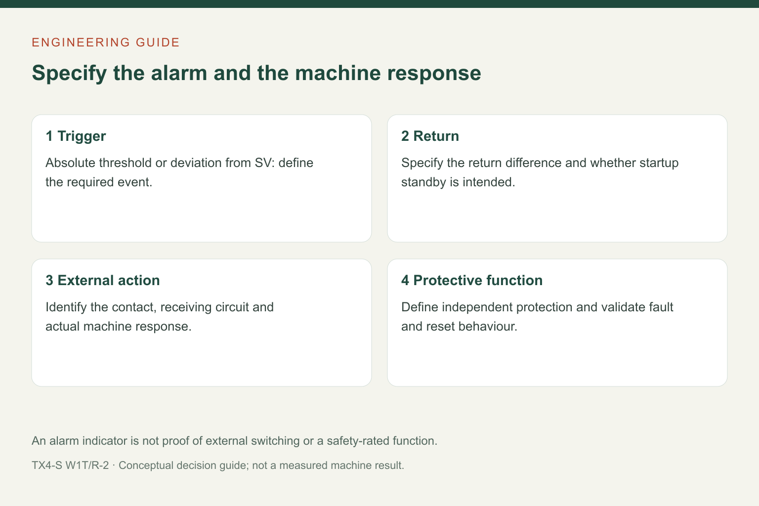
Configure a temperature-controller alarm around the condition that should trigger attention, then design the machine’s protective shutdown separately. A TX4 alarm contact can indicate a temperature event or pass a signal to another control circuit; it is not evidence of an independent safety-rated high-limit system. The correct setup starts with the exact alarm option, the intended response and a test plan for the whole machine.
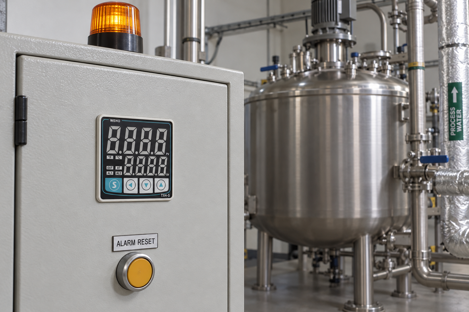
Start with the installed alarm option
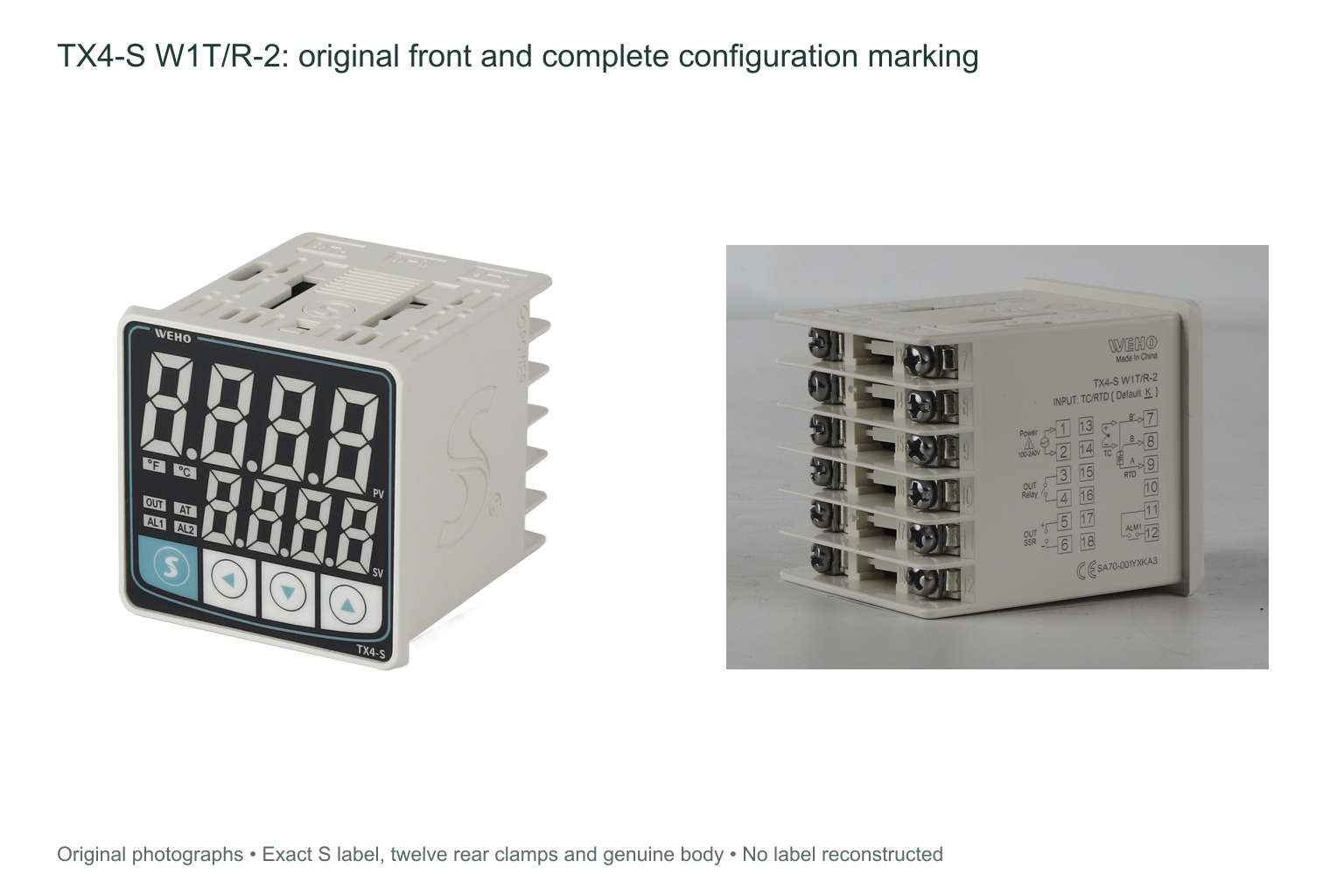
The pictured controller is TX4-S W1T/R-2. The ordering table distinguishes an Alarm 1 option from an Alarm 1/2 option, so a front face printed with both AL1 and AL2 does not prove that both outputs are installed. Confirm the full order code and the actual rear connection label before drawing the circuit.
The TX4 230808EN manual gives alarm settings in parameter groups P-1 and P-2 and illustrates their behaviour separately. Use the terminal drawing for the exact body size: a TX4-S connection arrangement must not be copied onto a TX4-M merely because the display layout looks similar.
Choose absolute or deviation behaviour
A deviation alarm follows the process set value. An absolute alarm uses a temperature threshold independent of that set value. This distinction matters when operators change recipes: the same numerical alarm entry can mean a different temperature boundary under the two modes.
| Buyer or machine requirement | Relevant alarm concept | What to confirm |
|---|---|---|
| Warn when temperature rises too far above the current recipe setpoint | High deviation alarm | The allowed offset and what happens after a recipe change. |
| Warn at a fixed process temperature | Absolute high-limit alarm | The fixed threshold, measurement location and receiving circuit. |
| Suppress an expected low-temperature alarm during initial warm-up | A documented standby alarm mode | The condition that releases standby and the consequence of a failed warm-up. |
| Remove heater energy following a hazardous temperature condition | A separately engineered protective function | Independent sensing, switching, reset and fault behaviour required by the machine design. |
For a conceptual example, a high-deviation setting of +10 degrees with an SV of 150 degrees targets a boundary around 160 degrees; changing SV changes that boundary. This arithmetic explains the mode only. It is not a recommended setpoint or protective limit for any pictured machine.
Define return behaviour and startup behaviour
The manual’s alarm return difference determines how far the temperature must return before the alarm clears. This reduces repeated switching near the boundary, but an excessively large return difference can leave an alarm active longer than the process team expects. Document both the activation and clearing conditions, including the temperature unit.
The standby function is also easy to misunderstand. The manual describes suppression of an existing startup alarm condition until the process first enters the non-alarm range. A standby low-limit alarm is therefore different from an alarm that must indicate an abnormal cold process immediately at power-up. Choose the function from the required sequence, not simply to silence an inconvenient light.
Give the external circuit a defined action
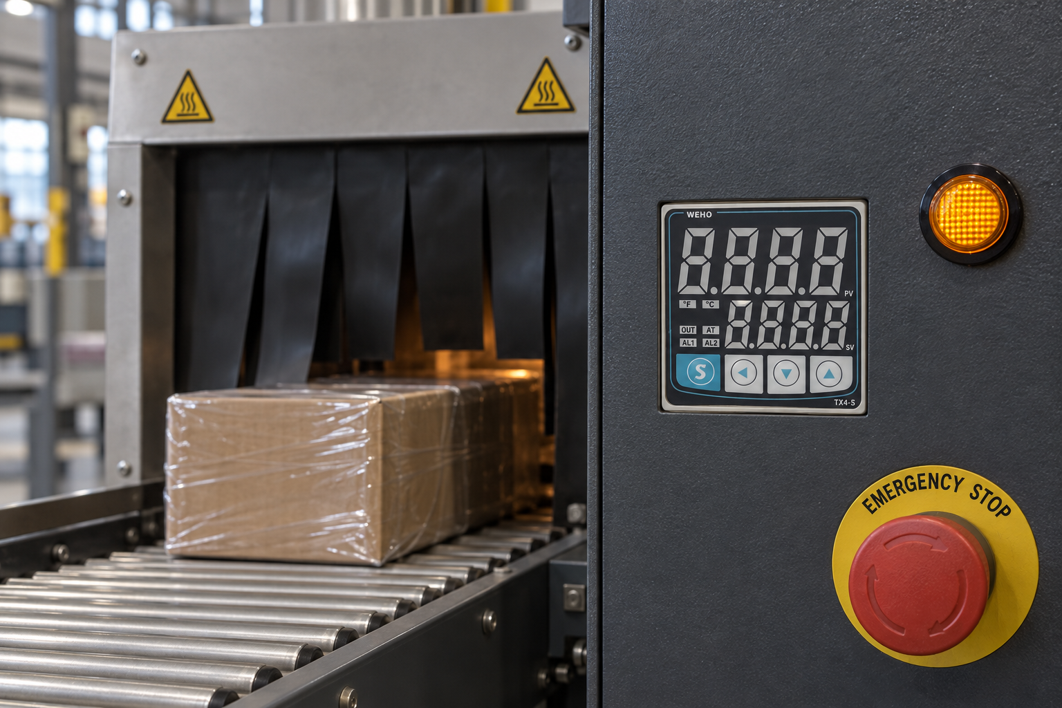
Specify what receives the alarm contact and what that device does: annunciation, a PLC event, a production inhibit or a separately engineered shutdown. Verify contact ratings, the actual load category and the receiving circuit. Do not assume that a controller alarm contact can directly switch the heater or a large contactor coil.
The manual requires an appropriate fail-safe device for machinery where a fault could create serious consequences. A process-control probe and its controller can share common failure modes. The machine designer must therefore establish the required independent protection rather than using a second indicator or software condition as proof of independence.
Test the full event path
- Record the exact controller code, alarm mode, threshold, return difference and startup option.
- Under the machine’s approved test procedure, check activation and clearing on both the controller and the receiving circuit.
- Verify the expected behaviour during startup, a recipe change, power interruption and relevant sensing faults.
- Confirm whether recovery is automatic or requires a deliberate reset, and who is authorised to restore production.
- Keep the results with the machine drawing and parameter record. Do not infer a tested protective function from an illuminated AL indicator.
Common specification questions
Is an AL1 indicator proof that the external circuit operated?
No. It indicates the controller’s alarm state. The external contact, wiring, receiving device and final machine action must be checked separately.
Should every alarm use standby?
No. Standby changes startup behaviour. Use it only where suppression of the initial condition is intentional and the machine’s fault response remains appropriate.
See the TX4-S controller page, или send WEHO an enquiry with the required alarm count, probe input, supply and output interface. Supply the intended machine response as a separate requirement so the alarm option is not mistaken for a complete protective design.




