When an RCD trips during transfer between an inverter and external AC, review the complete source, neutral and protective-earth arrangement in every operating state. A trip after reconnection does not identify a single fault or justify adding a neutral–earth bridge. Before integration, obtain the exact inverter and transfer-device instructions, a controlled system drawing and the responsible designer’s protection-verification plan.
This guide is for equipment integrators preparing an inverter/changeover specification. It explains what evidence to request and how to record an event. It is not a site wiring procedure or permission to alter neutral or protective connections.
1. Record exactly when and where the trip occurs
Identify the protective device that operated, the sources that were available and which source had been selected. Distinguish loss of external AC, transfer to the inverter, restoration of external AC and transfer back. Keep device indications and event times rather than reducing the report to “the inverter trips the RCD.”
A 2026 Victron Community report describes an RCBO operating when the priority source returns in a Filax installation. It demonstrates a real integration question, not a verified diagnosis. Its factory system and user-described connections must not be copied into a different installation.
Record whether the event happens with a particular connected load, after a delay, or only during one transfer direction. The qualified investigator can use those observations to select the appropriate tests. A correlation with switching does not establish whether the issue is cumulative leakage, a return-path problem, a switching condition or a fault.
For a steady installation-wide leakage budget, see multiple power supplies and RCD tripping. Transfer adds a separate question: does the approved protection arrangement remain appropriate when the active source and switching state change?
2. Build a four-state protection record
Use the electrical designer’s state descriptions. “Running” is too broad when an assembly can receive external AC, generate AC from an inverter, change source or be isolated for service. In each state, identify the relevant source, neutral arrangement, protective path and verification record. Do not fill unknown entries with assumptions from the enclosure or socket shape.
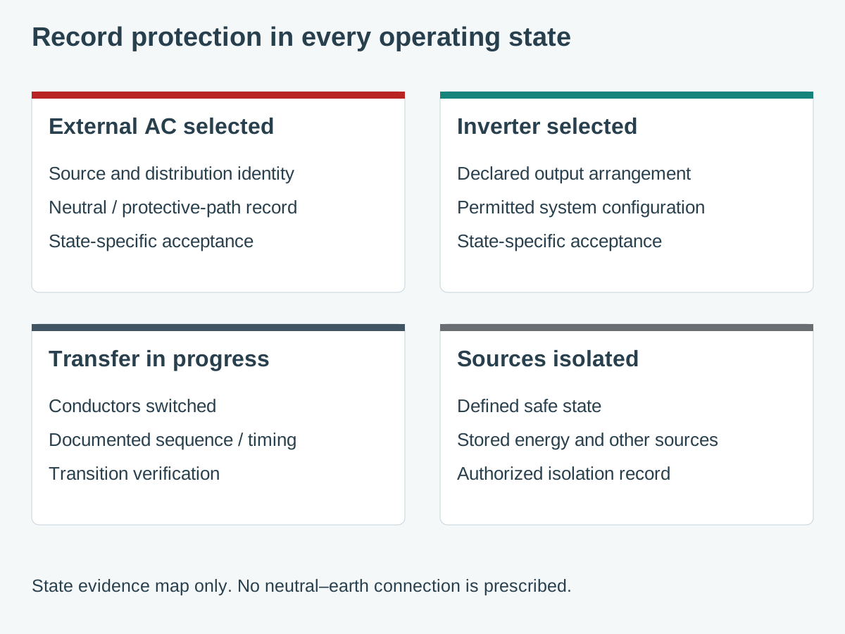
| สถานะ | Questions for the approved design | Evidence to retain |
|---|---|---|
| External AC selected | What source and distribution arrangement supplies the load? Which neutral and protective paths apply? | Source identity, current drawing and applicable protection verification. |
| Inverter selected | What output-system arrangement does the exact inverter permit? What protection is effective in this state? | Manufacturer instructions, approved design and state-specific results. |
| Transfer in progress | Which conductors change state, in what documented sequence, and what interruption or overlap can occur? | Transfer-device revision, sequence/timing evidence and approved test record. |
| Sources isolated | What constitutes the defined safe state, including stored energy and other connected sources? | Authorized isolation procedure and verification records. |
Victron’s grounding discussion illustrates why inverter and external-supply states require different consideration. It describes a ground relay in particular Victron inverter/chargers. That is an example of a documented product implementation; it does not establish a relay, bond location or switching function in a WEHO inverter.
The protective arrangement must suit the declared system and applicable installation requirements. This article does not prescribe one bonding rule or one RCD type for all vehicles, boats, buildings or inverter topologies.
3. Request the source and switching evidence together
For the inverter, request the exact configuration and installation revision, the declared AC output arrangement, protective-earth requirements and any documented limitations on external changeover equipment. Ask explicitly whether the requested neutral-related function exists; absence of a statement in a sales table is not a design confirmation.
For the transfer device, request which conductors it switches and its approved source arrangements, sequencing and fault behavior. A transfer-time number alone cannot identify all of those properties. Resolve inconsistent terminology or conflicting manual revisions with the manufacturer before accepting a system drawing.
ที่ Filax installation instructions are an example of product-specific source and protection requirements. They belong to that exact product. A compatible wattage or a similar terminal layout is not sufficient evidence that their arrangement can be transferred to another device.
Include the protective-device manufacturer’s requirements and the connected equipment in the review. Request device identity, permitted application, relevant current-waveform considerations and the test basis selected by the responsible designer. No trip sensitivity, operating time or conductor arrangement is specified here.
4. Keep candidate identity separate from system approval
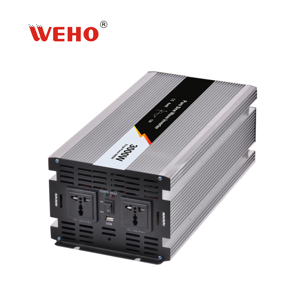
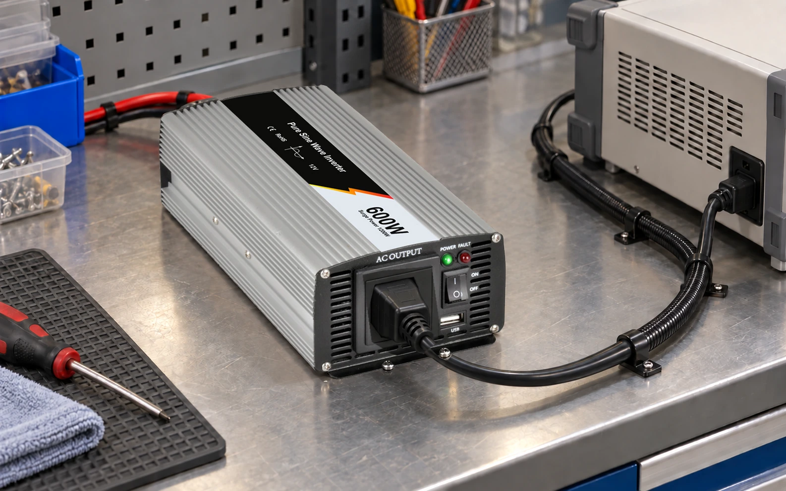
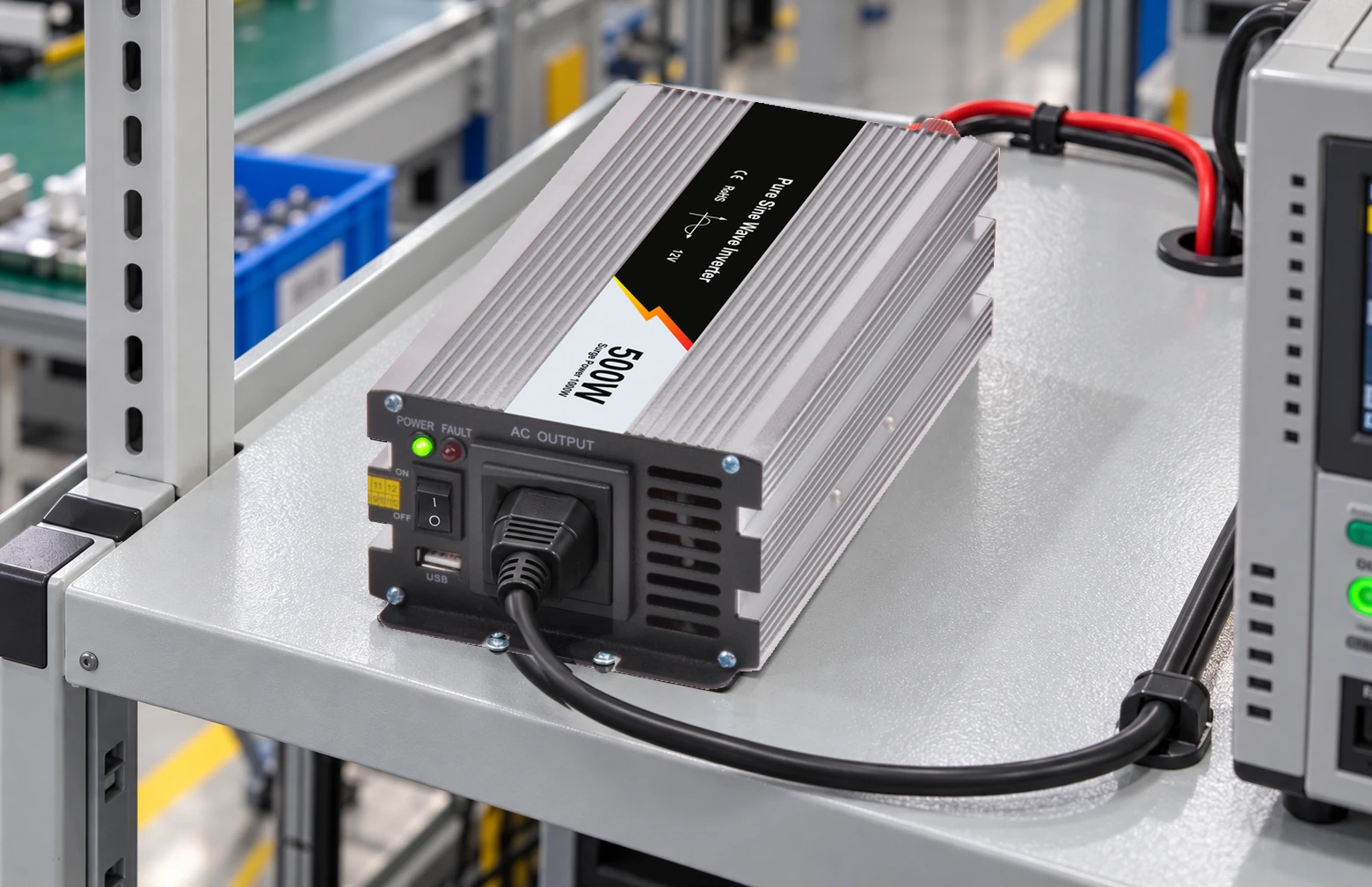
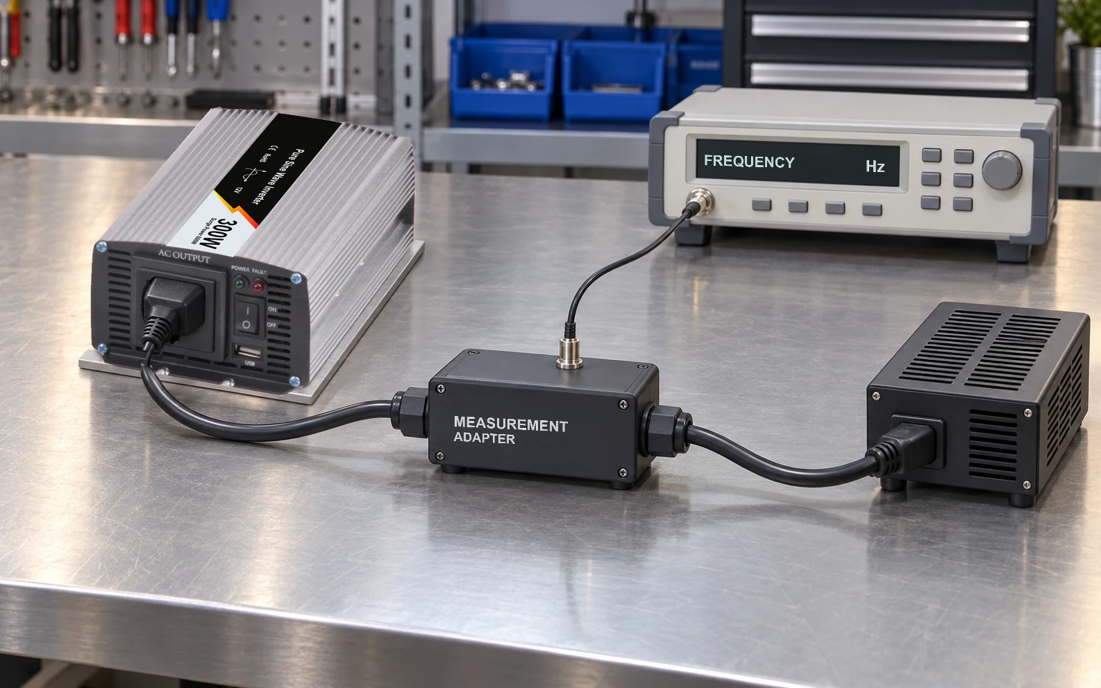
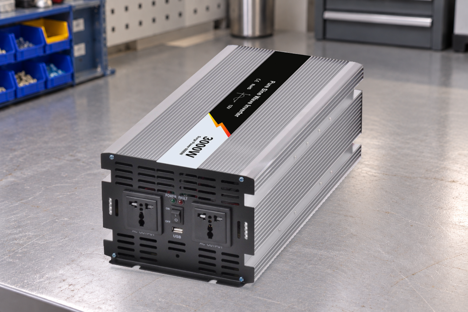
The pictured inverter is not presented as an inverter/charger, transfer switch or RCD-compatible system. The public product reference identifies a WHP inverter family; the exact AC output variant and the proposed protective arrangement require their own documents. A pure-sine-wave description does not answer a neutral-switching or protection-coordination question.
Have the supplier identify which requested functions are documented for the exact ordered configuration. If a required system function is outside the available product evidence, keep that requirement open or select an architecture with the necessary documented functions. Do not invent an internal connection to make the candidate fit.
5. Define verification and release responsibility
Before testing, the responsible qualified party should define the required operating states, transition events, protective-device checks, instruments and acceptance criteria under the applicable project requirements. The record should distinguish a successful functional transfer from verified protective performance; one does not prove the other.
Use controlled drawing and settings references so a later change of inverter, transfer device, source or protective device triggers the appropriate review. A photograph of connected equipment cannot prove the protective path or the behavior during an event hidden from view. For a separate bonding record, refer to protective-earth continuity and identified endpoints.
If the observed trip or protective behavior remains unexplained, retain the event record and refer it to the responsible designer and manufacturers. Do not bypass a protective device, remove protective earth or add a trial neutral–earth connection to suppress the symptom. Release the integration only after the required evidence and unresolved conditions have been closed by the responsible party.