A power supply current limit does not, by itself, limit the first discharge from a capacitor already charged across its output. Before adding bulk capacitance to a 24 V branch, review where that stored energy can flow during a wiring or receiver fault. Starting successfully and meeting a voltage-dip target are separate acceptance questions.
This article is for an OEM designer reviewing an external capacitor added downstream of a WEHO LRS-50-24. It provides an energy and fault-path record. It does not specify an approved capacitance, fuse, resistor or protection device for this supply.
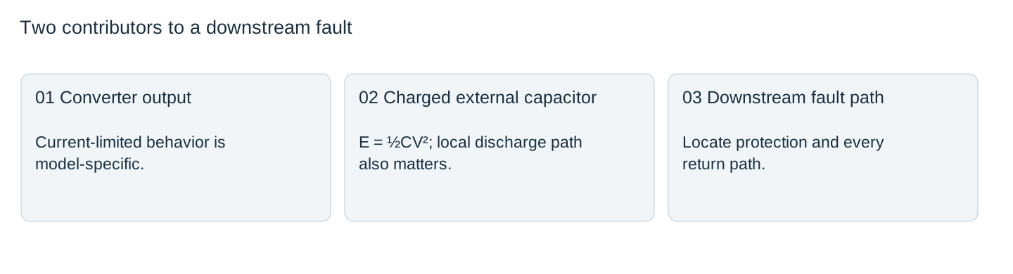
Draw the converter and capacitor as separate energy contributors
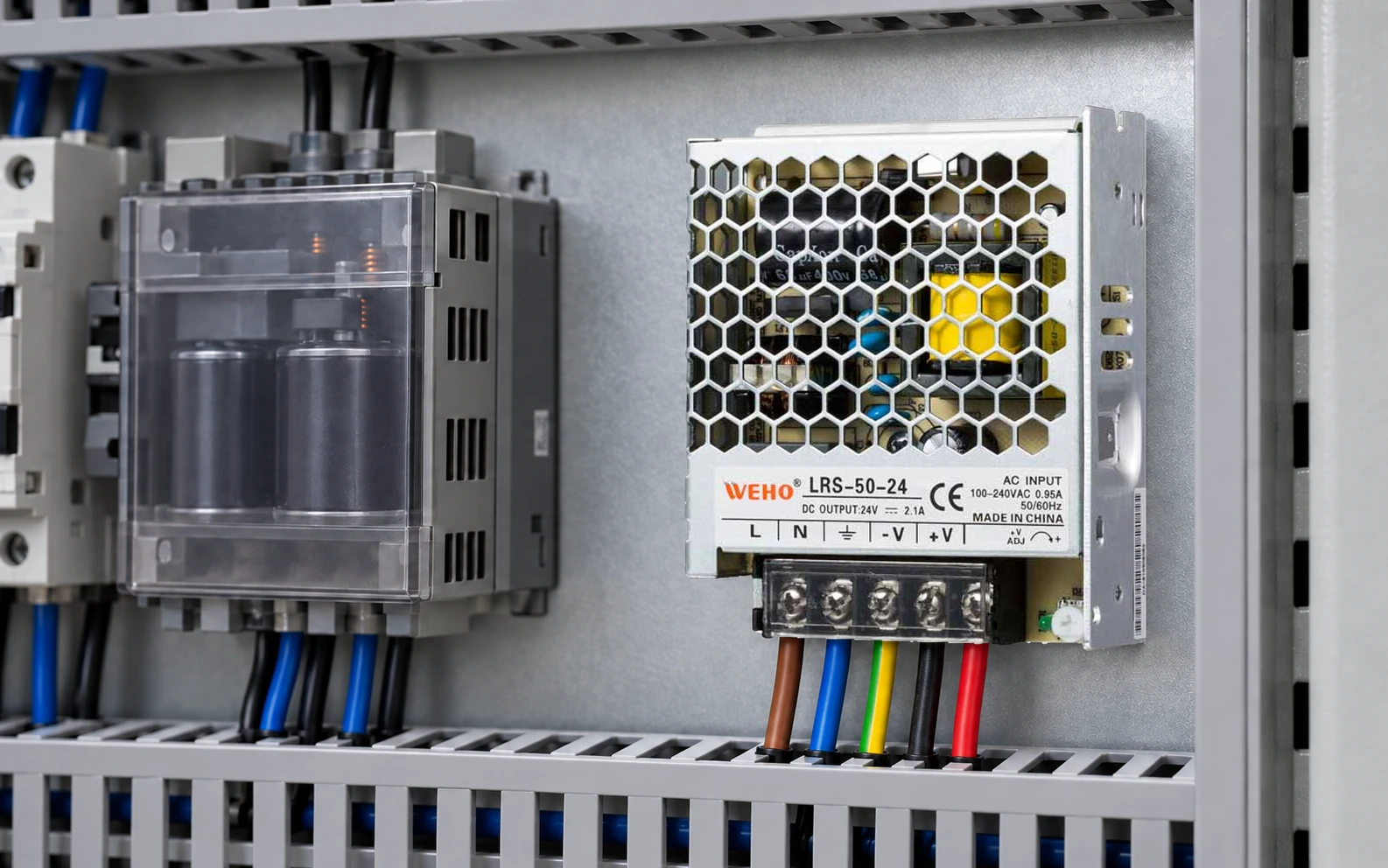
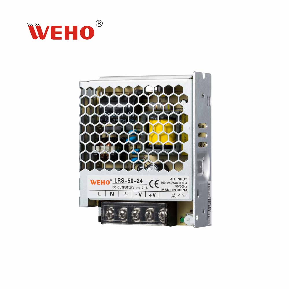
The LRS-50-24 manufacturer photograph is marked 24 V and 2.1 A. That output description is useful for identifying the pictured variant, but it is not a rating for every transient through an attached capacitor. During a fault, current may arrive both from the converter and from stored energy in the external branch.
Draw the external capacitor at its physical location, not merely next to the supply symbol. Trace its positive connection, return, receiver terminals, distribution protection and service connector. A protective device upstream of a capacitor can interrupt the supply path while the capacitor still has a local path to the fault.
Calculate stored energy before selecting a protective solution
For an ideal capacitor, E = ½CV², with capacitance in farads, voltage in volts and energy in joules. The TDK-Lambda hold-up explanation uses this energy relationship and also identifies startup problems introduced by extra output capacitance. Its product examples do not establish a WEHO limit.
As a hypothetical comparison at 24 V, 4,700 µF stores 0.5 × 0.0047 × 24² = 1.3536 J; 47,000 µF stores 13.536 J. Increasing capacitance tenfold increases this ideal energy tenfold. Neither result predicts a peak fault current or proves that a contact can interrupt it.
Use the actual maximum permitted branch voltage and the capacitance tolerance for a worst-case review. Energy varies with the square of voltage. ESR, ESL, conductor impedance, component failure behavior and the fault location shape the discharge. They must not be replaced with the converter current rating in the calculation.

Look for a discharge path that bypasses the intended protection
| Location to review | Question | Record needed |
|---|---|---|
| Capacitor near receiver | Is a short downstream of the capacitor also downstream of the fuse? | Physical circuit and protective-device position |
| Service connector | Can the capacitor remain on either half after separation? | Voltage and discharge-state record |
| Shared return | Can another branch complete a return path? | Complete return and bonding diagram |
| Receiver input | Is local stored energy covered by the receiver fault analysis? | Receiver limits and assembly assessment |
Do not move a fuse or add a discharge component from this table alone. Interrupting capability, coordination, component ratings, normal current and the relevant equipment requirements must be assessed together. The purpose of the path sketch is to expose a missing question before hardware is committed.
Keep startup, load support and fault response as distinct checks
First confirm the supply can start with the proposed capacitance under its stated input, load and environmental conditions. Then verify receiver voltage during the intended load event. Separately assess fault energy and isolation. Passing one check cannot substitute for the other two.
TDK-Lambda describes how an initially discharged capacitor can drive an ordinary constant-voltage supply into overcurrent protection. That is a reason to obtain the LRS-50 revision-specific permitted load conditions, rather than assume the added capacitor is harmless because its steady-state current is small.
Do not create uncontrolled shorts to obtain a dramatic current trace. A qualified test plan should state the approved fault simulation, protected test arrangement, instrumentation limits and stopping conditions. Retain the actual circuit revision and measured traces if such testing is authorized.
Release the capacitor as an assembly change
Record why the capacitor was added, its approved part and tolerance, the maximum operating voltage, the actual energy path and the remaining evidence. Reopen the review when the capacitor moves to another board or a field cable is shortened: the stored energy may be unchanged while the discharge path changes.
The useful release output is a signed circuit and evidence record, not a statement that a larger capacitor made the power supply stronger. If the fault-path assessment is incomplete, keep that assembly change out of the released BOM while continuing the independent supply and load checks.
For the proposed LRS-50-24 assembly, send the external-capacitance range, maximum permitted voltage, discharge-path sketch and protection record. Ask WEHO for the offered revision’s output-capacitance and startup conditions; qualify the downstream fault path separately with the equipment designer.
External capacitor change record
| Event | Energy or operating demand | Path and protection | Evidence | Karar |
|---|---|---|---|---|
Blank project worksheet. Enter verified project data; example calculations above are not measurements.