



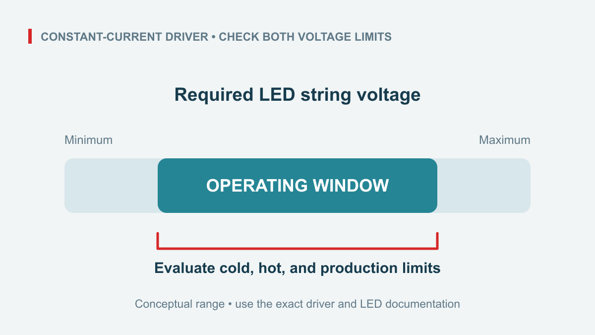
An LED driver’s output voltage depends on its output mode and operating state. For a constant-current driver, the LED string determines the required working voltage; that voltage must stay inside the driver’s documented constant-current window at the selected current. Check both ends of the window across LED variation, temperature, current tolerance, and connection losses. The advertised wattage, nominal output voltage, and maximum open-circuit voltage cannot replace this check.
مندرجات کا جدول
This guide gives luminaire OEM engineers a repeatable voltage-window screen. It concerns directly driven constant-current LED strings. LED strips with their own current-setting circuitry require a different constant-voltage or constant-current interface review.
Separate four output-voltage meanings
A constant-current driver adjusts its output voltage to establish the specified current through a compatible LED load. Its usable regulation range is bounded. A constant-voltage supply instead regulates a voltage while the connected circuit determines current within the supply’s limits. Some products have combined or programmable operating regions, so inspect the actual output characteristic.
| Entry | What it tells the engineer | What it does not establish |
|---|---|---|
| Nominal or rated output voltage | A specified operating point or voltage setting | The complete constant-current range |
| Constant-current window | Voltage range where the stated current regulation applies | Every startup or dimming condition |
| Open-circuit maximum | A specified unloaded-output boundary | Available continuous LED operating voltage |
| Overvoltage protection level | A protection threshold under defined conditions | A normal design target |
MEAN WELL’s LED drive-method explanation identifies LED forward-voltage variation and a model-dependent constant-current region. Its numerical examples describe its own products; they are not specifications for a WEHO driver.
Collect the LED and driver boundaries
Start with the LED module’s permitted current and forward-voltage limits, including the relevant temperature and manufacturing tolerances. Record how many devices are in series. Typical forward voltage at room temperature is insufficient for an enclosure that must start cold and operate hot.
Obtain the driver’s current accuracy, applicable constant-current window, input range, temperature limits, and any relationship between current setting and operating region. A selectable-current table may provide a different maximum voltage at each current. Keep voltage adjustment, current adjustment, and dimming commands separate in the review. Check the complete LED dimming control path separately.
Use connection resistance at the stated design condition. For a remote-driver layout, also complete the output-cable extension review. Include both conductors and connectors. When current varies within tolerance, use the appropriate current bound for each corner calculation. The LED voltage limits must themselves be valid at those currents; do not combine unrelated typical figures into a supposed worst case. MEAN WELL’s LED selection FAQ, question 3 similarly calls for checking both ends of the combined LED forward-voltage range.
Calculate the complete string window
Original hypothetical example, not a WEHO specification: consider a 700 mA driver with assumed current accuracy of ±3% and an assumed 30.0–42.0 V constant-current window throughout the conditions being reviewed. Each LED is specified, for this example, between 2.90 and 3.45 V over the complete current, temperature, and production range. The output circuit has 0.80 Ω total loop resistance at the chosen calculation condition.
The current limits are 0.700 × 0.97 = 0.679 A and 0.700 × 1.03 = 0.721 A. Corresponding connection drops are 0.5432 V and 0.5768 V. Required driver voltage is the sum of LED forward voltage and connection drop.
| LEDs in series | Minimum required voltage | Maximum required voltage | Arithmetic screen |
|---|---|---|---|
| 10 | 29.5432 V | 35.0768 V | Below lower window at minimum corner |
| 11 | 32.4432 V | 38.5268 V | Within assumed window |
| 12 | 35.3432 V | 41.9768 V | Only 0.0232 V below upper boundary |
| 13 | 38.2432 V | 45.4268 V | Exceeds upper window |
The 12-LED maximum is 12 × 3.45 + 0.721 × 0.80 = 41.9768 V. Rounding it to 42 V hides a nearly exhausted allowance. If the resistance assumption rises to 0.90 Ω, the result becomes 42.0489 V and exceeds the assumed window. A headline power rating cannot resolve this voltage limitation.
The 11-LED option passes this calculation under the stated assumptions. It has not been approved for startup, dimming, fault behavior, thermal performance, or production tolerance beyond those assumptions. Resolve those separately before selecting a driver or changing the string.
Interpret an out-of-window condition
Below the minimum constant-current voltage, the driver may no longer maintain its specified regulation. Above the maximum, it may be unable to deliver the required current. The resulting behavior could involve reduced current, cycling, shutdown, or another documented mode; do not predict it from the window alone.
Likewise, a successful room-temperature sample does not prove the limiting corner. The sample may have lower forward voltage than the production maximum, a shorter harness, or a different case temperature. Record the actual configuration rather than treating visible illumination as a complete pass.
Check startup, dimming, and disconnection
Review starting conditions separately from steady operation. Ask for the permitted load arrangement, startup behavior, dimming operating area, and output-disconnection instructions. An unloaded meter reading can reflect a protection or restart sequence and is not a reliable substitute for the specified constant-current window.
Ask specifically whether the proposed output connector may be disconnected or reconnected while energized. Depending on the driver design, open-load behavior and charge retained in the output stage can make reconnection a separate current-transient event. The open-circuit maximum alone does not predict the actual voltage trajectory, discharge time or protection response. MEAN WELL’s LED assembly guidance gives a manufacturer-specific example of possible surge damage when the LED load is connected after power is applied. Follow the selected driver’s own switching and discharge instructions rather than treating a secondary plug as a load switch.
Evaluate AC-side LED driver inrush current separately when switching upstream power. A steady output-voltage-window calculation establishes neither output hot-plug permission nor input-switch compatibility.
Keep a useful qualification record
Retain the exact driver model, suffix, document revision, current setting, LED bin or module specification, series count, harness revision, and temperature conditions. Link each boundary in the calculation to its source. Where the manufacturer gives only a typical value, identify the missing limit and obtain clarification instead of silently treating it as guaranteed.
Define acceptance criteria before testing the assembly. Separate output-current accuracy, successful startup, dimming behavior, electrical output limits, and relevant temperatures. Qualified personnel should use the manufacturer’s test and isolation instructions. A generic multimeter procedure cannot establish every dynamic or unloaded-output condition.
Request the exact operating limits
Contact WEHO about an LED-string driver through the contact form with permitted current, minimum and maximum string forward voltage, series count and connection losses, plus the input and temperature conditions. Request the corresponding operating-region and startup documentation so the candidate can be evaluated against the actual load.




