A 12 V to 5 V converter for USB power must be evaluated as one stage of the equipment. Producing 5 V at the converter leads establishes an electrical rail. It does not establish USB current advertisement, connection handling, a charging protocol, or compatibility with a particular device and cable.
For an OEM design, define the port role first, allocate power to the downstream interface, then qualify the converter and port together. A higher converter current rating does not replace the interface evidence. This article addresses a source port powered by the equipment, rather than a product receiving its own input through USB. For a fixed 5 V equipment rail without a USB port, compare direct and cascaded DC conversion; where USB or other cables add return paths, review non-isolated shared-return grounding.
Article sections
Specify the port the equipment must provide
Write down the connector, power role, intended devices, supported cables, number of ports, simultaneous loading and whether data transfer is required. Decide whether the design calls for a fixed 5 V Type-C source or a USB Power Delivery implementation with an explicitly defined capability set. A Type-C connector and USB PD are separate decisions.
The TI USB Type-C and Power Delivery primer distinguishes power conversion from connection logic and PD communication. Use that distinction when dividing responsibilities between the converter supplier and interface designer.
For detailed interface requirements, record the applicable USB specification revision and the chosen controller’s supported implementation. Calling the requirement “USB charging” leaves too much undefined for a repeatable supplier comparison. An architecture overview is useful context; the qualification record should identify the actual interface being built.
Separate the 5 V rail from the source interface
A useful block diagram has a converter boundary and a separate port boundary. Between them, identify the controlled power path and any protection the interface needs. The port drawing must show which functions are actually present, rather than assume they exist inside the DC converter.
A fixed 5 V stage alone cannot generate higher USB PD voltage profiles. Supporting such profiles requires suitable additional power conversion and PD control; their placement depends on the complete architecture. Adding communication logic does not by itself create another output voltage. Even a fixed 5 V port still needs its applicable source-interface functions.
| Boundary | Evidence to request | What a 5 V converter label cannot establish |
|---|---|---|
| DC conversion | Input range, output tolerance, load response, ripple conditions and thermal requirements | Behavior of a USB connector or attached device |
| Type-C source interface | Connection detection, current advertisement, power-path control and applicable discharge behavior | Correct source behavior from voltage alone |
| USB PD, if required | Supported source capabilities, policy/controller implementation and validation records | PD communication or negotiated power from a fixed output |
| Installed port | Connector, cable, protection and equipment-level verification | End-to-end performance from a converter current rating |
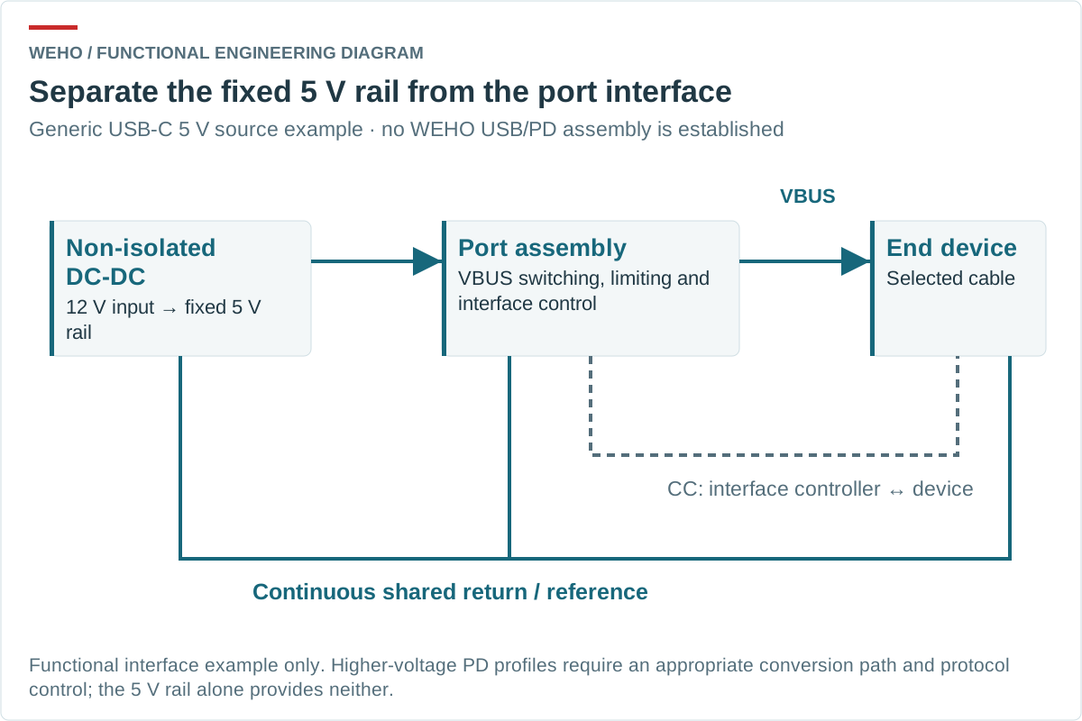
For example, the TI TPS25820/21 source-controller datasheet describes CC monitoring, current advertisement and a controlled USB power switch. It illustrates a different functional role from a DC converter. It is not evidence that this controller and any WEHO converter form a verified combination.
Budget the shared DC rail before allocating ports
Consider a hypothetical power budget for two downstream source-interface assemblies. Assume each assembly draws 1.50 A from a 5.00 V converter rail at the selected simultaneous operating point, and common control circuitry draws another 0.10 A. These are assumed DC-rail currents, not measured device charging currents or advertised USB capabilities.
Irail = 1.50 + 1.50 + 0.10 = 3.10 A. The converter output budget is 5.00 × 3.10 = 15.50 W. If converter efficiency is assumed to be 90% at this point, input power is 15.50 ÷ 0.90 = 17.22 W. At 12.00 V measured at the converter input, input current is 17.22 ÷ 12.00 = 1.44 A, rounded.
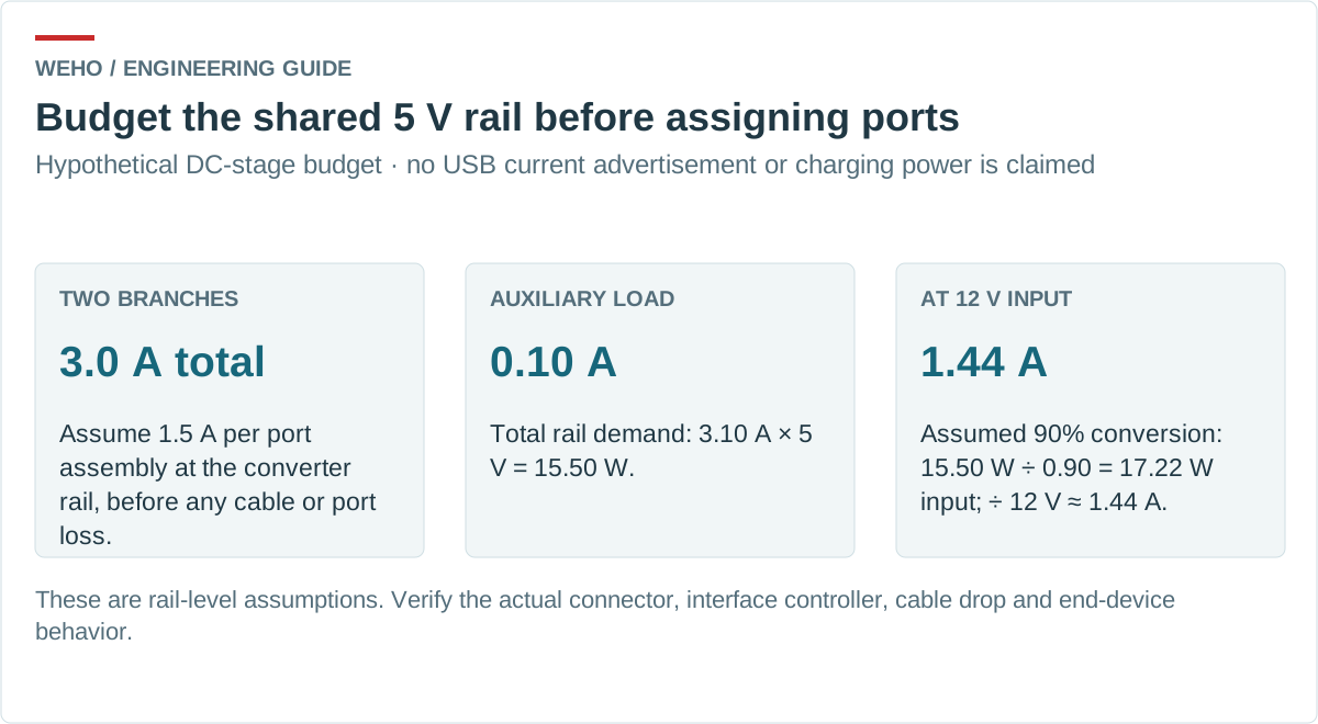
The 90% value is an assumption for arithmetic, not a WEHO measurement. This budget does not include an unspecified reserve or prove startup capability. For repeatable input/output readings, use a defined converter-efficiency measurement boundary. If simultaneous demand is restricted by a controller, document how that allocation is communicated and enforced.
Check the worst-case converter output tolerance together with power-switch, trace, connector and allowed cable drops. Identify which voltage limit applies at the source port and which applies at the connected device under the selected USB requirements. A nominal 5 V reading at the converter leads cannot close that voltage budget or establish behavior during connection events.
Verify attach, detach and fault states together
Test the complete interface with its selected converter, controller configuration, cables and representative loads. Record the 5 V rail and port voltage as different measurement points. Check both connector orientations where applicable, attachment while other ports are loaded, detachment, removal of the upstream supply and recovery after a permitted port fault.
Define the expected result for each state: what is powered, what current is allowed, how the output changes and what the equipment reports. A successful charge indication on one device does not establish the full supported device population, and a steady resistor load does not exercise connection management.
Coordinate port protection with the converter’s documented fault behavior. Record each port’s current-limit settings, switched capacitance, connection ramp and fault-response timing. Check whether attaching one port or limiting a single-port fault disturbs the shared rail enough to reset a controller or interrupt another permitted load. Do not assume a 10 A converter’s overcurrent protection will adequately protect a lower-current port. Also review paths through data cables or other powered interfaces: a non-isolated converter does not separate their reference potentials.
Review WH-C12240510 as a DC-stage candidate
The WEHO WH-C12240510 product details identify a non-isolated step-down converter with a published 9–32 V input range and 5 V, 10 A, 50 W output rating. Its model-specific specification PDF provides the associated electrical rows. Input and output share a negative connection.
Those figures support reviewing the item as a candidate DC stage. They do not establish a USB connector, Type-C controller, PD support, a battery-charging profile or permission to pass 10 A through one USB cable. The nameplate power also does not approve the hypothetical two-port assembly.
Obtain the applicable controlled document revision and output conditions required by the selected interface. Check the minimum voltage actually reaching the converter and the allowed rail variation during port events. The published 9 V input floor is not evidence of regulation below that value.
Send a port requirement with the converter inquiry
Send WEHO the DC-stage requirements for your USB-powered interface, with the following information:
- Actual equipment input range and simultaneous 5 V rail loads, measured at declared boundaries.
- Port role, connector, supported devices/cables and the applicable interface revision or controller document.
- Per-port current limits, switched capacitance, connection ramps, fault timing and allowable shared-rail disturbance.
- Required rail/port voltage limits, mounting and thermal conditions.
Keep the acceptance record in two parts: converter electrical performance and complete port behavior. That division makes the supplier’s evidence useful without turning a fixed 5 V supply into an unsupported USB product claim.