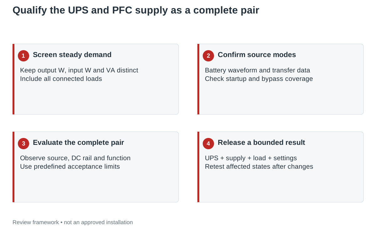
Qualify the UPS and PFC supply as one input pair across startup, battery operation and source transfers. A PFC claim and a suitable steady wattage do not establish that the supply will stay within its requirements during every UPS mode.
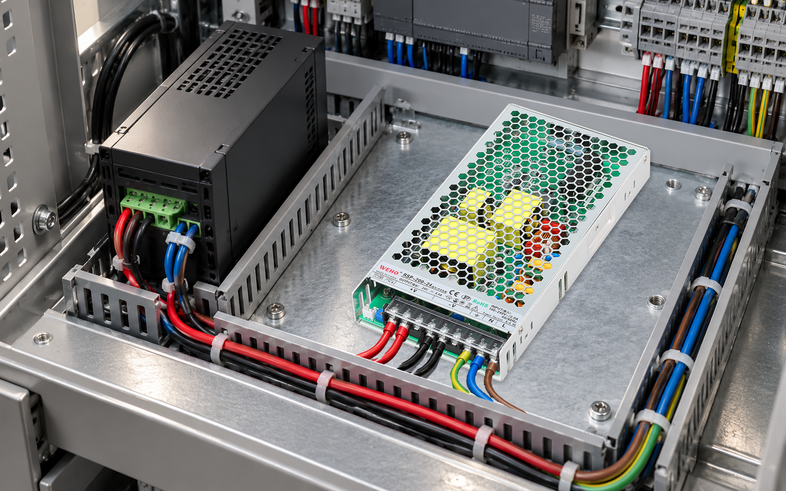
This guide helps an OEM engineer prepare a pairing review using the WEHO RSP-200-24 as the supply reference. It defines the evidence and acceptance record to request; it does not identify a UPS that has been validated with this model.
Read the published PFC condition, then keep it in scope
The RSP-200W page lists power factor of at least 0.99 at 115 V AC and at least 0.95 at 230 V AC, both at full load. Those figures describe stated test conditions. They do not specify the behavior on every battery-mode waveform or during transfer between sources.
The same product information identifies a broad operating input range and steady electrical data. Confirm the exact supplied revision and the actual DC load before sizing the project. A family wattage or output-label figure cannot be used directly as the UPS input demand. This guide separates the initial power estimate from the evidence needed to approve the complete pair.
APC’s UPS selection guidance associates pure-sine-wave battery output with improved compatibility for active-PFC equipment. That helps identify a source characteristic to discuss; it is not evidence that a particular UPS and RSP supply have been tested together.
Use watts and VA as an initial screen
Hypothetical calculation, not an RSP-200 measurement: suppose the intended DC load is 120 W, the assumed supply efficiency at that condition is 0.90 and the assumed input power factor is 0.95. These are example assumptions, not copied RSP operating guarantees.
| Quantity | Calculation | Illustrative result |
|---|---|---|
| Supply real input power | 120 W ÷0.90 | 133.3 W |
| Supply apparent input power | 133.3 W ÷0.95 | 140.4 VA |
| Additional loads | Add their documented input demands separately. | Not included in this example. |
| Startup and transfer demand | Requires separate data or evaluation. | Cannot be derived from 140.4 VA alone. |
This screen prevents confusing DC output watts with total AC demand. It does not establish runtime, peak input current or transfer ride-through. Use measured or confirmed efficiency and power factor at the actual load for a real project, and evaluate the UPS’s independent W and VA limits.
Request the source and load information as one record
Schneider Electric’s Smart-UPS guidance for non-IT loads warns that industrial and scientific loads can need a separate compatibility assessment. It recommends collecting steady demand, peak inrush, inrush duration and equipment identities. Apply that evidence-first approach to the complete intended assembly rather than assuming an industrial panel behaves like a computer load.
| Pairing question | Information to collect | What the review must resolve |
|---|---|---|
| Battery-mode source | UPS waveform, voltage/frequency limits and output arrangement. | Coverage of the supply’s permitted input conditions. |
| Startup | Supply and all other loads starting; source state and peak duration. | Whether the UPS supports the actual starting event. |
| Transfer and return | Transfer behavior, source recovery and any operating restrictions. | Whether downstream voltage and function meet project limits. |
| Sustained battery operation | Expected load window, runtime requirement and thermal conditions. | Performance through the required operating interval. |
| Bypass or alternative mode | Every permitted source path and its characteristics. | Whether the accepted configuration covers those modes. |
Define functional acceptance before collecting results
Set criteria at the equipment load as well as at the supply. A controller can reset, a communication link can drop or an actuator can enter an unwanted state even when the supply eventually returns to its nominal voltage. Record the permitted interruption, output excursion and recovery behavior for the machine.
Use a controlled test plan with the actual UPS, supply revision, intended load and relevant configuration settings. The responsible team should define instrument access, event capture and operating states. A single successful mains-to-battery transition is evidence for that run, not every load, battery condition or source mode.
Include startup while on battery if it is an allowed operating state. Include return to mains and any repeated transitions required by the use case. Preserve UPS alarms, supply output observations and controller status on the same event timeline so a failure can be assigned to the right part of the system.
Respond to a failed transfer without guessing the cause
If a controller resets, compare the observed source event, supply output and controller input requirements. An output dip, UPS overload alarm and control-system restart can occur together without proving which started the event. Retain the waveform or event record and the exact load condition before changing components.
Do not assume that buying a higher VA number resolves waveform, transfer or inrush limitations. A different topology or manufacturer-confirmed pairing may be needed. Recheck the affected states after a corrective change rather than carrying forward the earlier compatibility claim.
Release the tested pair and its operating window
Record the UPS model and firmware/configuration, supply revision, other connected loads, battery condition and accepted modes. Keep the manufacturer responses and actual test results with the blank PFC-supply/UPS pairing record. Reassess the affected checks after a material change to any of those items.
The final statement should identify the pair and conditions that were evaluated. A PFC logo or a computed 140.4 VA estimate is a starting point for that work, not a completed compatibility result.
Use the project record
Open the blank PFC power supply and UPS pairing record to record your conditions, evidence and decisions. The worksheet contains no pre-approved result.
Prepare a supply-and-UPS pairing review
Send WEHO the RSP-200-24 requirement, intended UPS model and modes, actual DC load profile and permitted interruption/restart behavior. Request the applicable input, startup and ride-through information for the supplied revision, and coordinate the pairing assessment with the UPS manufacturer.