



- A four-wire resistance result describes the electrical path between the actual sense points.
- Separate force and sense leads, and place sense contacts at the boundaries of the intended joint.
- Two valid Kelvin setups can report different values when one includes extra conductor or crimp resistance.
- Use an isolated test arrangement and applicable contact-test conditions; the example is not an energized cabinet procedure.
Why two four-wire readings can disagree
A production team receives a 0.6 mΩ joint result from one fixture and a 1.5 mΩ result from another. Both instruments use four wires, so the team first questions the calibration. Before replacing equipment, compare the actual sense-contact locations and determine whether the fixtures measure the same physical boundary.
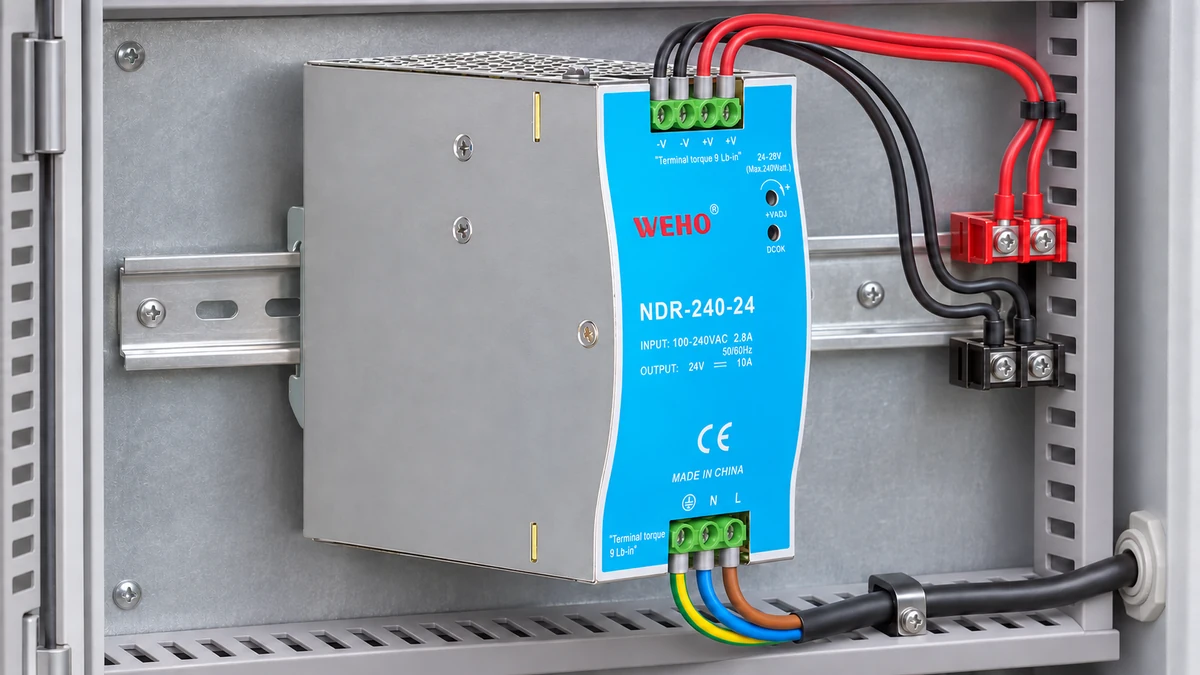
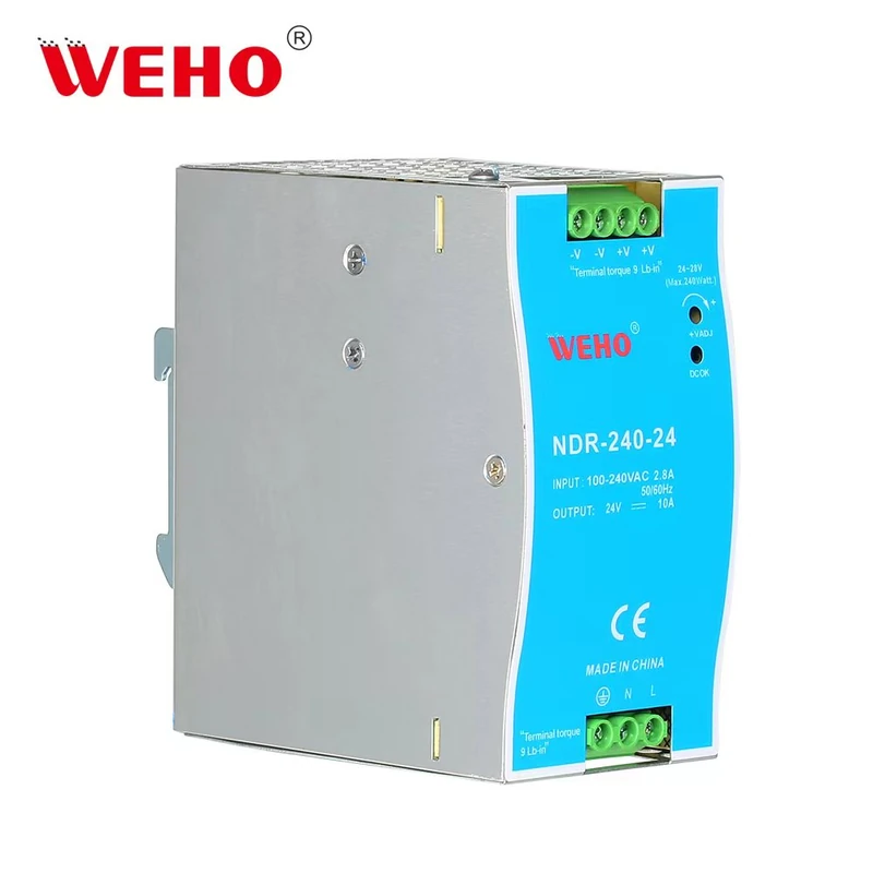
The WEHO NDR-240-24 product reference provides a cabinet-distribution context for this task. The contact under investigation is an external connection defined by the integrator, not the internal resistance of the supply. Nothing here establishes remote-sense terminals or permission to modify an NDR-240-24.
Define the resistance being accepted
Write the acceptance requirement as a named path between two physical points. “Contact resistance below 1 mΩ” is incomplete if the measurement may include the mating interface, conductor length, crimps, screw connection or several of these together. Mark both boundaries on a drawing and a photograph before setting a numerical limit.
Keep local joint assessment separate from end-to-end distribution assessment. A low-resistance mating interface can coexist with a larger complete path resistance because conductors and crimps contribute additional voltage drop. Those results answer different questions and should be stored with different measurement names.
Carry the accepted path values into a separate 24 V load-voltage budget when assessing the installed branch. That calculation uses the complete distribution path; the present task establishes which portion a local four-wire resistance result actually represents.
Identify whether the requirement concerns a new assembly, a conditioned sample or a connection after an environmental or mechanical exposure. Contact condition, assembly process and the allowed test current can change the result. Do not compare readings from different sample states as though only the measuring instrument changed.
Separate force current from voltage sensing
The four-wire method uses one lead pair to force test current and another pair to sense voltage across the selected path. The Keithley low-level measurement handbook explains this arrangement for low resistance and contact measurement. Resistance is calculated from the sensed voltage and the applicable test current.
Place the sense contacts so they bound the intended resistance while the force contacts establish the required current path through it. Separate terminals at the instrument do not help if force and sense are joined at the wrong place on a long test lead. The physical connections at the sample are part of the measurement definition.
NI's low-level switching guide describes measuring voltage directly across the resistance under test to exclude force-lead voltage drops. Excluding those drops does not exclude conductor or contact resistance deliberately located between the sense points. Four-wire describes the connection method; it does not automatically select the correct product boundary.
Work a hypothetical sense-boundary comparison
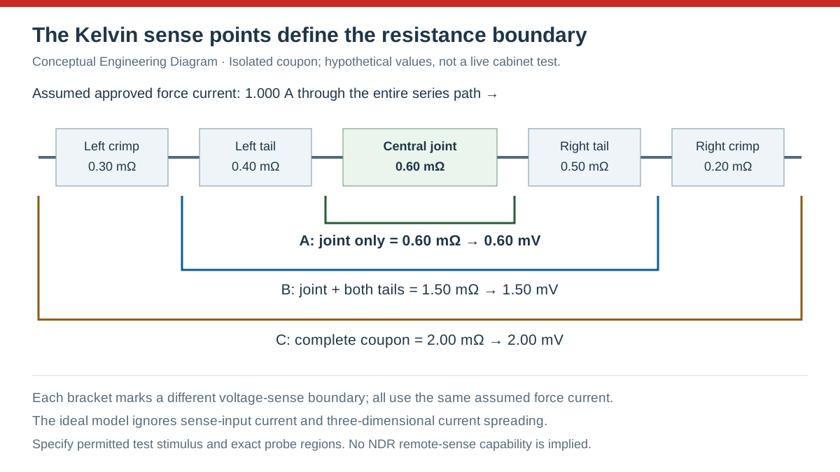
Assume an isolated external joint coupon is approved for a 1.000 A test current. Its left conductor segment is 0.40 mΩ, the central joint is 0.60 mΩ and its right conductor segment is 0.50 mΩ. Additional outer crimps contribute 0.30 mΩ on the left and 0.20 mΩ on the right.
These are invented values for a boundary calculation, not measurements of a WEHO terminal or instructions to apply 1 A to an assembled machine. Assume uniform current through the series path and negligible sense-input current for this ideal model. An actual contact-test requirement must establish the allowed source and sample conditions.
With sense points immediately across the central joint, V = I × R = 1.000 × 0.00060 = 0.00060 V, or 0.60 mV. Dividing by the test current gives 0.60 mΩ. The conductor segments, outer crimps and external force leads are outside that chosen voltage boundary.
Moving the sense points outward to include both conductor segments gives R = 0.40 + 0.60 + 0.50 = 1.50 mΩ and V = 1.50 mV. Including the two outer crimps gives 2.00 mΩ and 2.00 mV. All three results can be correct in the assumed series model because they describe different paths.
| Sense boundary | Included series elements | Voltage at assumed 1.000 A | Reported resistance |
|---|---|---|---|
| A: local joint | Joint only | 0.60 mV | 0.60 mΩ |
| B: joint plus tails | 0.40 + 0.60 + 0.50 mΩ | 1.50 mV | 1.50 mΩ |
| C: complete coupon | Two tails, joint and two outer crimps | 2.00 mV | 2.00 mΩ |
An illustrative 1.00 mΩ local-joint limit is passed by boundary A in this exact-value example. Boundary B cannot be substituted to judge that local requirement because it includes additional resistance. Conversely, an A result cannot establish a separate end-to-end path limit; actual near-limit decisions also need the agreed measurement allowance.
Swipe horizontally on a small screen, or open the full-size diagram.
Make fixture placement reproducible
Define each sense point by a drawing feature and an acceptable contact region, not a vague instruction such as “near the screw.” Probe tips on a screw head, lug surface and conductor can enclose different paths. The assembly's geometry determines whether a convenient exposed surface represents the intended electrical boundary.
Avoid placing the sense contacts where concentrated force-current injection creates an unrepresentative potential distribution. In an actual three-dimensional joint, spreading resistance and local geometry can matter, so a simple series diagram is only a starting point. Qualify the fixture against the required contact-test method and representative sample construction.
Keysight's lead-resistance measurement guide explains using separate current and sense pairs to reduce wiring contributions. Preserve that separation through any switches, connectors and fixture interfaces relevant to the measurement. A four-wire instrument connected through an undocumented two-wire fixture section can retain an unwanted resistance term.
Preserve the contact state during the test
Select test current, open-circuit voltage, duration and any conditioning from the applicable requirement and the contact manufacturer's information. A high test stimulus can alter the surface condition of some contacts, while a long dwell can introduce heating. An assumed 1 A example does not establish the correct stimulus for a different contact or interface.
Use a de-energized, isolated specimen or an expressly designed test arrangement that prevents other sources from influencing the resistance measurement. Connected loads, parallel conductors or stored energy can invalidate the assumed current path and create hazards. Four-wire ohms testing is not a reason to connect an ordinary resistance instrument across an energized supply output.
This article resolves the force/sense location question rather than every low-level measurement error. Instrument uncertainty, settling, thermal conditions and offsets still belong in the applicable method. Changing those controls cannot repair a fixture that measures the wrong physical boundary.
Release a boundary-controlled measurement method
- Name the accepted path. Mark the two sense boundaries and the included contact or conductor elements. Save the drawing and requirement revision; accept the definition when different reviewers identify the same physical path.
- Map force and sense contacts. Record the four sample connections, fixture interfaces and permitted probe regions. Verify continuity and isolation in the prepared fixture; accept only a configuration that establishes the intended current and voltage paths.
- Set the approved test conditions. Record stimulus, range, compliance, duration and specimen state from the applicable method. Accept the setup when the equipment and sample limits support those conditions without unapproved conditioning.
- Repeat the placement check. Reconnect representative samples using the written fixture procedure and compare the resulting records. Use a project-defined repeatability criterion; investigate placement-sensitive changes before using the fixture for production acceptance.
- Store the result with its boundary. Save voltage, current, calculated resistance, uncertainty treatment and a connection photograph. Apply the correct limit to that named path; prevent a local-joint result from being relabeled as complete-harness acceptance.
Keep fixture maintenance and sample changes in the same record system. Worn tips, alternate lugs or a changed contact region can modify the measurement even when the instrument program is unchanged. Revalidate affected placement details before comparing new data with historical results.
Prepare an NDR-240-24 connection enquiry
Send WEHO the NDR-240-24 candidate, external connection drawing, conductor and termination details and the boundary being investigated. Ask for applicable terminal instructions while keeping your external contact-test method and acceptance criteria explicit. Use the WEHO contact page to share the assembly conditions without treating a generic Kelvin diagram as a product-terminal approval.
Frequently asked questions
Do four wires automatically measure only the contact interface?
No, the voltage sense points define the included path. Conductor, crimp or other joint resistance between those points remains part of the reported value.
Can two correct four-wire fixtures report different resistance?
Yes, fixtures can measure different physical boundaries. Compare the sample connections and included elements before attributing the difference to calibration.
Can I use the 1 A example as a universal contact-test current?
No, the example assumes a coupon already approved for that stimulus. Select actual current, voltage and duration from the applicable contact-test requirements and sample limits.
Does the Kelvin diagram establish remote-sense capability on NDR-240-24?
No, the diagram concerns an isolated external contact measurement. It does not identify remote-sense terminals, modify the supply or authorize an energized resistance test.



