A low-resistance test can include an unwanted thermoelectric voltage as well as the contact's resistive drop. Where the instrument and test method support it, reversing the test current helps distinguish those contributions.
- Use separate current and voltage connections for a four-wire measurement.
- Reverse equal test currents and retain the signed voltage readings.
- Keep a bench resistance result separate from operating-temperature acceptance.
Why might a sound connection appear to change resistance?
A small temperature difference across dissimilar-metal connections can generate a thermoelectric voltage. When the resistive drop being measured is also very small, that added voltage can distort the calculated resistance. Changing a clip or touching a terminal may alter both contact quality and the thermal conditions of the measurement.
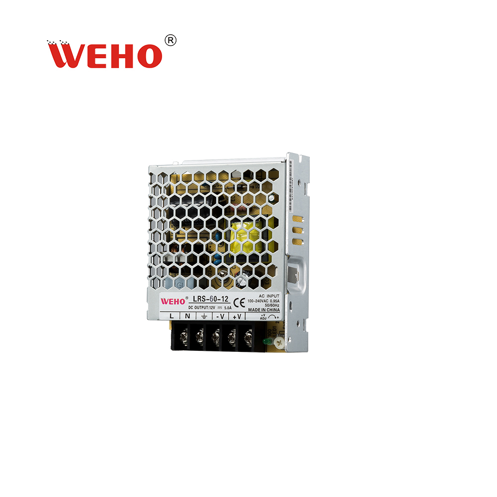
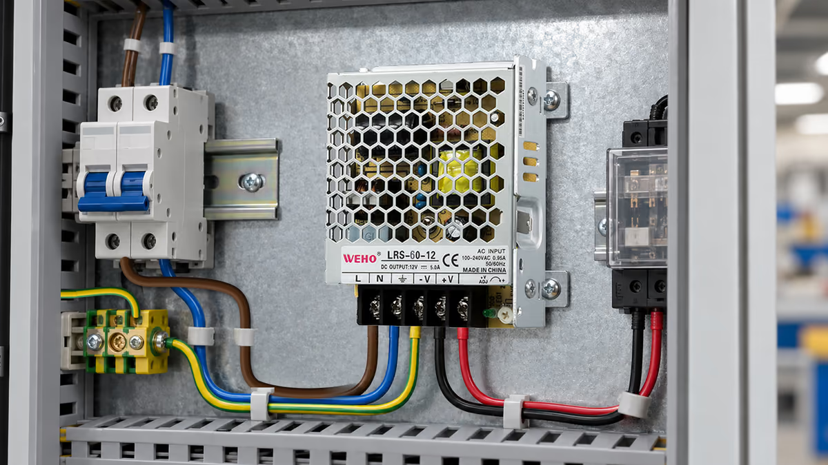
An OEM reviewing an LRS-60 power-supply assembly may need to evaluate a removable connector, splice or separate terminal joint. The correct test boundary is that defined connection, not the entire energized supply. Do not inject an ohmmeter's current into connected electronics without a procedure confirming that the circuit is suitable.
This article addresses resistance metrology on an isolated test specimen. It does not specify LRS-60-12 terminal torque, permissible temperature rise, current rating or an approved joint resistance. Those acceptance limits belong to the applicable component documentation and project requirements.
A resistance number should answer a defined question. Is the objective screening an assembly process, diagnosing an intermittent joint, or comparing a design change? Each may require different current, mechanical conditioning and temperature control. A more detailed instrument display does not remove those differences.
How does current reversal separate resistance from offset?
Assume the contact behaves linearly over the selected test interval and the unwanted thermal voltage stays constant during two readings. For equal positive and negative test currents, the signed voltages are V+ = I × R + E and V− = −I × R + E.
Subtracting the readings removes the constant offset: R = (V+ − V−) ÷ (2 × I). Their average estimates E. Reversal does not cancel changing offsets, nonlinearity or unstable contacts, so the sequence still needs a controlled method.
Consider a hypothetical isolated connection with R = 2.0 mΩ, I = 0.100 A and E = 40 µV. The forward reading is 240 µV; the reverse reading is −160 µV. Using only the forward reading produces 2.4 mΩ, while the two-reading calculation produces 2.0 mΩ.
The example's 20% single-reading difference comes from the chosen offset and current. It is not a prediction for any WEHO assembly. The same 40 µV offset matters less when the resistive voltage is larger, but increasing test current can heat the specimen or change the contact being assessed.
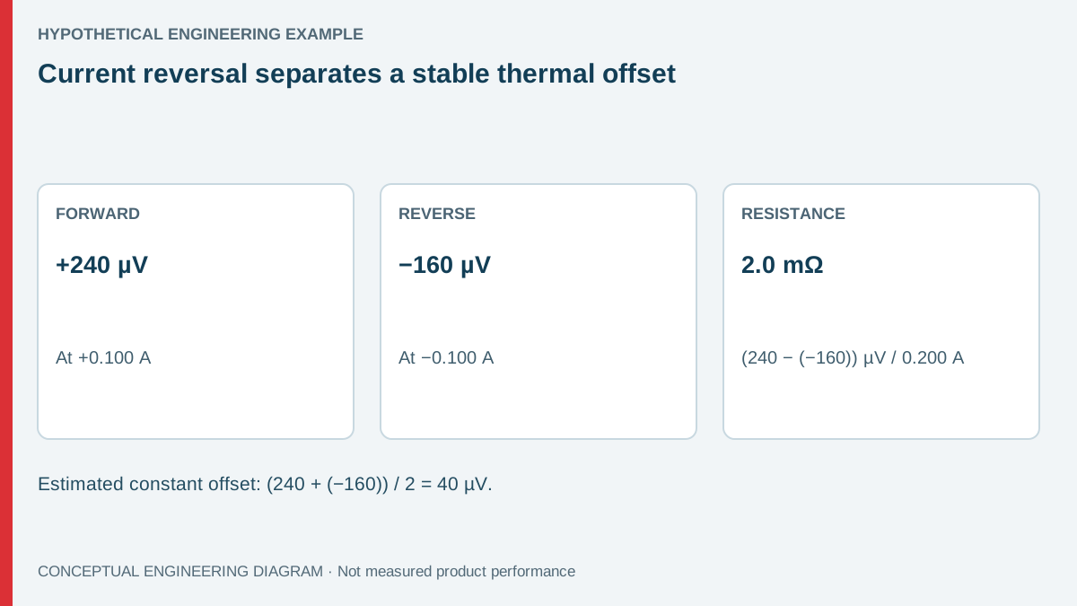
| Observation | Example value | Interpretation | Remaining limitation |
|---|---|---|---|
| Forward signed voltage | +240 µV at +0.100 A | Resistive drop plus offset | One polarity cannot separate them |
| Reverse signed voltage | −160 µV at −0.100 A | Reversed resistive drop plus offset | Offset must remain sufficiently stable |
| Reversal resistance | 2.0 mΩ | 400 µV divided by 0.200 A | Depends on actual current and signed readings |
| Estimated offset | 40 µV | Average of the two signed readings | Does not identify the physical source alone |
What does four-wire measurement change?
Four-wire measurement separates the current-carrying leads from the voltage-sensing leads. The sense points define the measured specimen. Placing them outside a connector can include nearby conductor resistance; placing them across only one interface can exclude other joints that matter in service.
Document those points with an annotated photograph or drawing. “Four-wire test” describes a method, not a complete boundary. Two technicians can obtain different valid results if one includes a crimp and the other measures only a mating contact.
Use the instrument manufacturer's supported low-resistance method. Some instruments perform offset compensation or current reversal internally; others require separate control. Check actual current direction, settling time and polarity convention before applying the arithmetic manually. Do not reverse a connected supply's operating power to imitate this test.
For primary measurement guidance, Keithley's low-resistance drift application note covers low-resistance techniques and unwanted voltage effects. Its methods must be adapted to a suitable specimen; it does not provide a WEHO acceptance resistance.
How should the test sequence control temperature and mechanics?
Let the disconnected specimen and measuring connections approach a documented condition. Avoid changing clips, touching sensitive joints or introducing airflow between the paired readings. The goal is not a universal waiting period; it is demonstrating that the sequence is stable enough for the decision.
- Define and isolate the specimen using the equipment's energy-isolation procedure.
- Confirm that the proposed test current is appropriate for its components and purpose.
- Connect separate force and sense leads at documented locations.
- Record both polarities, actual currents and the time between readings.
- Repeat the sequence to check drift and reproducibility before deciding acceptance.
If the second pair differs materially from the first, investigate the cause instead of averaging away the change. Temperature drift, moving contacts, oxide films, thermoelectric offsets and an inappropriate range can all matter. Repeating a flawed setup does not make its result more representative.
Mechanical state belongs in the record. Capture mating condition, connector identity, assembly procedure and any specified conditioning. A resistance result after manipulating a suspect connection may not describe the original fault state. Preserve the initial observation when investigating a field return.
How does the bench result relate to operating heat?
An isolated resistance test and an operating temperature-rise test answer different questions. The first helps characterize a defined current path under its test conditions. The second includes service current, enclosure conditions, heat paths and any temperature dependence of the joint.
For a purely illustrative operating calculation, a 2.0 mΩ joint carrying 3.0 A dissipates I²R = 0.018 W. If the same joint rises to 20 mΩ, the arithmetic becomes 0.180 W. Those numbers do not establish a temperature because thermal resistance and surrounding heat sources have not been specified.
The LRS-60 family product information identifies the supply being integrated. Use the applicable supply, connector and terminal documentation for their respective requirements. A low measured joint resistance does not independently approve the complete wiring assembly or its protective arrangements.
When a supplier receives only “resistance too high,” it cannot determine whether the disagreement concerns a joint, a lead, an offset or a test condition. Include the specimen boundary and signed raw readings. That allows recalculation and makes a repeat test more useful than a comparison of isolated final numbers.
A four-wire fixture should also control the sense-contact location from sample to sample. Moving a sense point along a conductor changes the included resistance, even when the connector itself is unchanged. Marking the intended locations on the fixture drawing can make repeated assembly checks more consistent.
Where the instrument uses unequal positive and negative currents, the simple equal-current denominator above is not directly applicable. Use the actual supported compensation method and recorded currents. A spreadsheet that assumes equal magnitudes without checking them can reintroduce an error after the thermal offset has otherwise been addressed.
Prepare a connection-test discussion
Send WEHO the supply variant, separate connection drawing, current path and measurement record relevant to the integration question. Include any applicable connector acceptance requirement and the instrument method. Keep supplier-specific assembly requirements separate from the hypothetical calculations above so that each decision has a traceable basis.
Frequently asked questions
Does four-wire measurement remove thermal EMF automatically?
No. It reduces the influence of force-lead resistance when implemented correctly, but a voltage offset can remain in the sensing circuit. A supported compensation or reversal method addresses a different source of error.
Can test current simply be increased until the result stabilizes?
Only within an appropriate validated method. Higher current can heat the specimen or alter a contact condition. Check instrument, component and test-purpose limits before changing it.
Is the reverse reading always negative?
Not necessarily. A sufficiently large offset can exceed the reversed resistive drop. Preserve signed readings and actual currents; do not replace the negative reading with its absolute value in the reversal formula.
Does passing the resistance test approve the installation?
No. Current capacity, insulation, mechanical retention, temperature rise and protective measures remain separate checks. The resistance test supports its defined connection question and documented conditions.