



For IO-Link, identify the communication supply and the auxiliary actuator supply before choosing a power supply. Port Class A and Port Class B do not make every 24 V source interchangeable. A Class B interface adds a separate power task, with requirements for isolation, available current and behavior when that extra power fails.
The WEHO HDR-15-24 is a documented 24 V, 0.63 A product. It is used here to demonstrate a small supply-budget review, not as a blanket recommendation for an IO-Link master or a Class B actuator. Confirm the actual master, device and electrical-safety requirements before approving any pairing.
Follow the power task through the master to the device
các IO-Link Interface and System Specification V1.1.3, sections 5.4 and 5.5, distinguishes Power 1 for communication from the additional Power 2 of Class B. It calls for Power 2 to remain electrically isolated from Power 1 and for communication to continue when Power 2 fails. These are interface requirements to check in the complete design, not capabilities established by a supply’s nominal voltage.
| Interface task | What to identify | Evidence owner |
|---|---|---|
| Power 1: master / communication / device electronics | Master input consumption; port supply demand; communication requirements. | Exact master and device manuals. |
| Power 2: Class B auxiliary load | Separate actuator demand, current limits and isolation arrangement. | Master, actuator and system design records. |
| Power supply | Output capability and required safety/application documentation. | Exact supply specification and supporting records. |
A cable with more conductors does not create an independent supply. Likewise, splitting one output pair into two branches does not by itself provide isolation between those branches. Follow the electrical architecture in the chosen master’s manual rather than adding links based on a generic diagram.
Do not reuse Class A pin assumptions on Class B
Beckhoff’s IO-Link master connection guidance explains that a Class A module may assign an additional digital function to pin 2, while Class B uses pins 2 and 5 for an extra supply. It directs users to the specific module documentation. A five-pin connector’s appearance therefore does not tell you how its contacts are assigned in the selected port.
Record port class, device type, connector view, cable assembly and the required auxiliary-power conductors. Keep Class A optional digital functions separate from Class B power in the interface record. A cable substitution needs review even if both ends screw into place.
The exact master also determines per-port and aggregate limits. A bank of individually acceptable sensors can still exceed a shared supply or master input limit when operated together. Keep the upstream supply budget, the master’s own consumption and downstream port limits as separate entries.
Work through a small, hypothetical Power 1 budget
các WEHO HDR-15 product table Và HDR-15 specification sheet agree that HDR-15-24 is the 24 V, 0–0.63 A variant. The following arithmetic uses invented loads solely to show the review method; it is not a test of any IO-Link product.
| Hypothetical demand on one supply | Hiện hành | Budget treatment |
|---|---|---|
| Master electronics, excluding the listed devices | 0.18 A | Count once; confirm how the real manual defines consumption. |
| Two sensor electronics loads | 2 × 0.10 A = 0.20 A | Confirm both their supply path and port limits. |
| Power 1 subtotal | 0.38 A | 9.12 W at nominal 24 V. |
| Proposed auxiliary actuator | 0.40 A | Do not silently merge into the Power 1 budget. |
The subtotal leaves 0.63 − 0.38 = 0.25 A of arithmetic capacity. Adding the hypothetical actuator to that same source would require 0.78 A, exceeding 0.63 A before any additional allowance. More importantly, the combined sum alone would not establish the Class B isolation arrangement even if a larger supply were used.
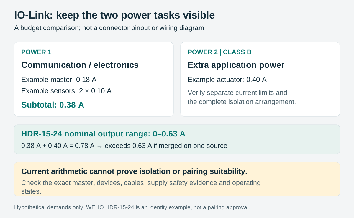
For a real budget, replace every number with a maximum demand under a defined state. Include startup, simultaneous devices, output loads that the master powers, cable voltage drop and the applicable temperature limits. Check whether the master’s quoted input current already includes its port loads to avoid double counting.
Require more than a successful connection
Before treating HDR-15-24 as a candidate for a small branch, establish the required supply safety classification, voltage range at the master, peak demand and environmental limits. A withstand-voltage entry is not by itself a complete declaration that the source meets every IO-Link SELV or isolation requirement. Obtain the exact supporting documentation for the intended unit and architecture.
Document which source feeds each master supply input and which downstream functions depend on it. For the auxiliary branch, verify how isolation is maintained through the master, actuator, cable shields and any other connections. Do not join returns simply because both are labelled 0 V.
Then define an acceptance procedure from the master and device manuals. Check the demanding simultaneous load state, device voltage at the intended cable length and recovery after the permitted auxiliary-power interruption. Use a controlled procedure that keeps machine motion and process hazards managed. The result must state what was observed, rather than simply “IO-Link works.”
Release the port configuration with the power budget
Keep the port class and configuration, master firmware, connected device revisions, cable part numbers, two supply budgets and electrical-safety evidence in one handoff record. If an extra-power failure is part of the test, retain both the actuator state and communication result.
Reopen the review when changing a sensor to an actuator, enabling a digital output, replacing a cable or populating an unused port. Each change can alter the actual supply task even if the nominal system voltage remains 24 V. This record lets purchasing and service teams distinguish a documented small branch from an unverified expansion.
Use the project record
Open the blank IO-Link port-power responsibility and release record to record your conditions, evidence and decisions. The worksheet contains no pre-approved result.
For an HDR-15-24 enquiry, provide the intended branch budget and the master manufacturer’s supply requirements. Ask WEHO for the applicable product revision and supporting electrical-safety documents; approve the complete IO-Link pairing separately.




