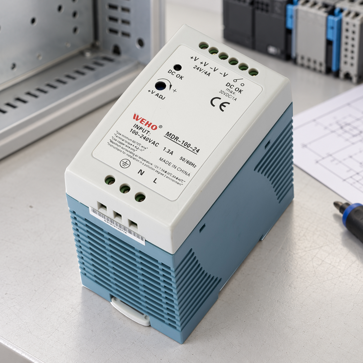
An industrial power supply’s DC-OK contact is useful only when the control system can receive, interpret and act on it. Record the contact state, PLC input state and resulting machine action as separate events. Also establish how the record survives if the monitored supply powers the PLC itself.
On this page
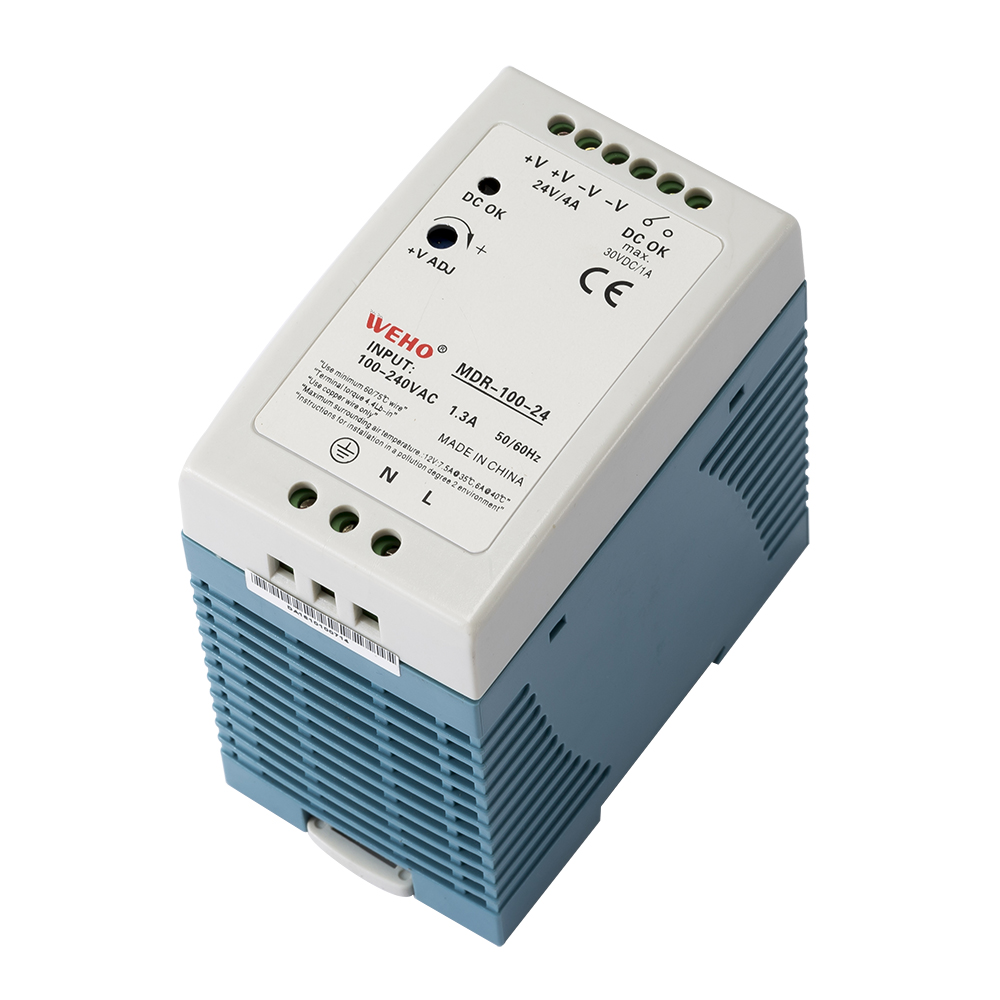
This guide uses the WEHO MDR-100-24 original product photograph to define an OEM response test. It addresses the path from a power-status indication to a documented control response, rather than treating the presence of an alarm terminal as proof that the equipment will stop or recover correctly.
Read the MDR-100-24 marking before designing the input
The photographed panel has a local DC OK indicator and two separate DC OK contact terminals carrying a switch symbol and a maximum 30 VDC / 1 A marking. The local visual indication is distinct from the external contact interface. That marking is a contact-rating observation; it does not specify the voltage threshold, minimum switching load, delay, insulation classification or response to every internal failure.
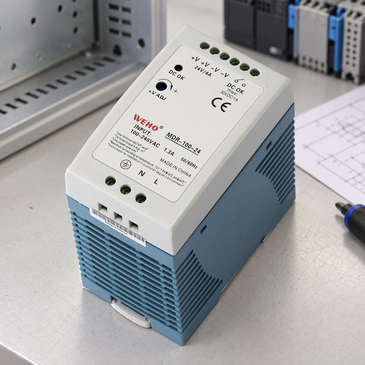
Use the exact MDR-100 product detail page for the enquiry and request the applicable contact/terminal specification. Confirm the receiving PLC module’s voltage/current requirements and input circuit before approving a connection. The maximum contact marking alone does not authorize a particular wetting supply, input topology or connection to an external circuit.
Follow the event through the complete control path
DC-OK behavior is model-specific. For example, a PULS manufacturer specification separately defines its contact’s monitored quantity, switching thresholds and treatment of short dips. The useful lesson is the required level of documentation; those settings do not belong to the MDR-100-24.
Next, distinguish the electrical input from the value used by the program. Siemens’ DI module manual explains that configured input delay affects whether and when a signal change is detected. Use the actual installed module, configuration and task behavior when establishing the equipment response.
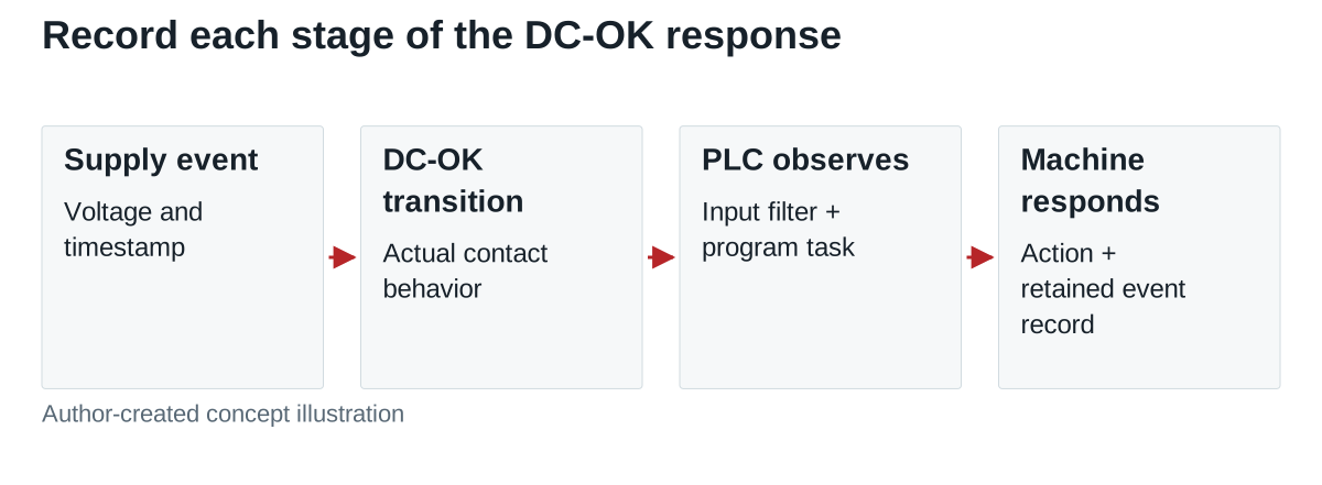
| Observation point | Record | Question it resolves |
|---|---|---|
| Supply output | Measured voltage at identified source terminals and event time | What electrical event actually occurred? |
| DC-OK contact | Contact state, transition time and applicable contact definition | Did this model indicate the event? |
| PLC input | Module/channel, input reference, raw/filtered state and filter setting | Was the indication accepted by the input? |
| Control program | Task/cycle, alarm condition, latch/reset and output command | Did the software execute the intended response? |
| Machine response | Actual actuator/drive state and time to the required condition | Did the equipment achieve the project requirement? |
| Surviving evidence | Recorder power source, timestamps and retained event file | Can the sequence still be inspected after power loss? |
Budget the response without inventing a relay delay
Hypothetical timing budget: a project requires a commanded response within 50 ms after the monitored event. Assume a verified contact-detection bound of 10 ms, an input-processing bound of 8 ms, a worst-case program wait of 12 ms and an output-command bound of 5 ms. Their sum is 35 ms, leaving 15 ms against that stated requirement.
These are invented design assumptions for the worksheet, not MDR or PLC specifications. Replace each with a documented bound or a measured result under the defined test conditions. Include communication latency if remote I/O is involved. Actuator movement may take longer than the output command, so give the final physical response its own requirement and observation.
Keep the test observable when control power disappears
If the MDR supply also powers the PLC, the controller may lose operating voltage before it can save or transmit an alarm. Record which devices remain powered during each test. An independent recorder or an appropriately designed retained control-power arrangement may be needed to observe the complete sequence.
Test mains removal, an approved output-dip scenario, an opened signal conductor and a controller restart as separate cases where applicable. Use a controlled test arrangement; do not create an unsafe fault to force an indication. Define the expected contact/input state and alarm retention for each case before running it.
Include a brief event that ends before the configured input delay and a sustained event that should be recorded. Compare both with the stated response requirement. A missing alarm may be the documented filter behavior rather than a failed relay; the acceptance record should make that distinction visible.
An opened conductor can resemble a loss-of-OK state in some approved circuits, but the software cannot automatically identify the cause. Record the actual diagnostic coverage rather than labelling every alarm “power supply failed.”
Release the response record with the machine program
Request the MDR-100-24 contact specification from WEHO with the required response and receiving PLC input details. Retain the returned document with the exact supply identity, PLC module and settings, program revision, test conditions and synchronized event results. Specify who clears a latched indication and what permits restart after the supply recovers.
The final acceptance record should demonstrate the path from a defined event to the required equipment response. A standard DC-OK contact provides status information; using that information for any safety function requires the separately established equipment safety architecture and validation.