Power supply transient response is meaningful only when the load step and the acceptance window are defined. Specify initial and final current, rise and fall time, repetition, measurement point and permitted voltage excursion. A static regulation percentage cannot replace this record.
On this page
This guide helps an OEM compare a supply’s dynamic behavior with an equipment event such as a valve bank switching or a processor subsystem waking. It does not present a measured WEHO waveform or a universal transient limit.
Describe the event the load actually creates
A step from 1 A to 6 A changes demand by 5 A. If that change occurs in 10 μs, its average slew rate is 0.5 A/μs. The same current change over 10 ms is a different test. Record both directions: removing load can create a voltage overshoot even when the rising-load undershoot is acceptable.
Also state pulse duration, repetition and which other branches are active. A short pulse can draw on stored energy; a long pulse challenges sustained current and temperature. The duty cycle may affect average heating, but it does not erase the peak-voltage requirement.
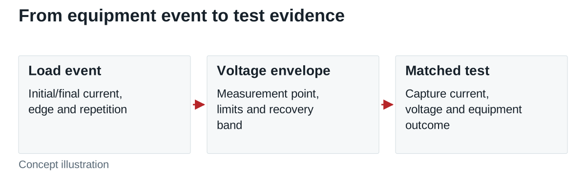
Build the voltage envelope first
In a hypothetical 24 V system, suppose the load’s permitted operating range is 22.8–25.2 V, including the specified transient events. A nominal 24.0 V source leaves 1.2 V on either side only before accounting for steady-state accuracy, conductor drop, ripple and measurement uncertainty. Allocate those contributions without automatically adding unrelated worst cases as though they always coincide.
| Record field | Example definition | Why it matters |
|---|---|---|
| Load step | 1 A to 6 A and back; 10 μs transition | Sets magnitude, direction and slew rate |
| Measurement location | At the equipment’s DC input connector | Includes the harness seen by the equipment |
| Voltage bounds | 22.8–25.2 V in this assumed example | Makes overshoot and undershoot acceptance explicit |
| Recovery criterion | Return to an agreed steady band within a stated time | A peak-only result does not establish settling |
| Operating corners | Relevant input, temperature, capacitance and other loads | Prevents comparing unlike conditions |
Identify whether a short excursion outside the continuous band is permitted by a separately documented time-dependent limit. Do not invent that permission because the equipment survived one test. A normal-looking restart after a dip can still fail the required operating behavior.
Use a capacitor estimate as a screen
For a deliberately simplified estimate, assume the entire extra 5 A is initially supplied by an ideal 500 μF capacitor. A 0.6 V drop takes t = CΔV/ΔI = 60 μs under a constant current deficit. If an assumed effective series resistance is 20 mΩ, its initial resistive contribution is 5 A × 0.020 Ω = 0.10 V.
These calculations explain what information matters; they do not predict a complete supply response. They neglect the evolving converter current, harness inductance, other capacitors and control-loop behavior. Additional capacitance also needs the selected supply’s stability, startup and allowed-capacitance review, rather than being treated as an unrestricted cure.
Measure the current step as well as voltage
TI AN-1733 explains practical transient testing and measurement limitations. Short, suitable measurement connections and a sufficiently fast current measurement help distinguish the intended event from test-fixture artifacts. Do not copy a regulator-specific test circuit as a mains-supply test procedure.
Confirm that the electronic load produces the specified edge at the DUT, rather than relying only on its programmed setting. Record the measurement bandwidth, probe arrangement, current edge and voltage trace together. A long cable between source and electronic load may become an important part of the measured response.
TI’s explanation of undershoot and overshoot identifies current-change rate, magnitude and control/output-stage factors as contributors. Its particular converter feature and example performance are not specifications for another product.
Name RSP-500-24 in the load-step test request
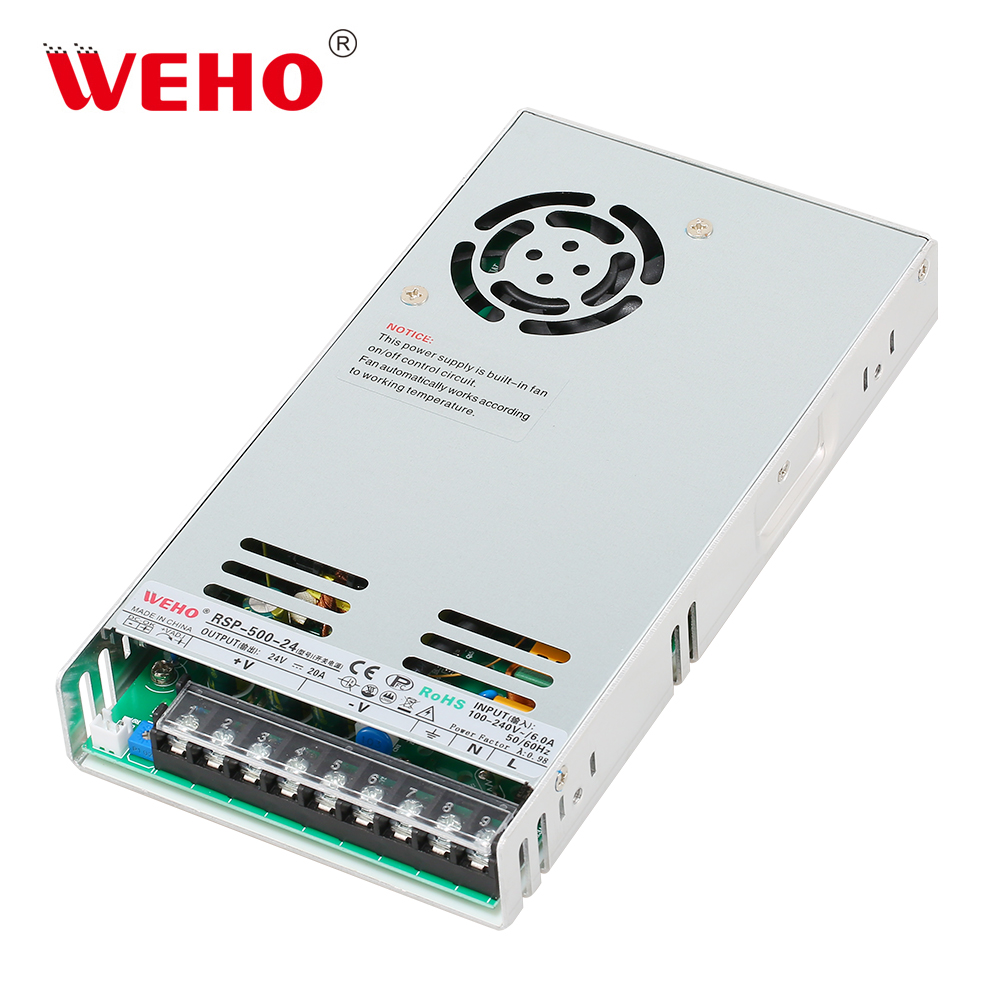
For a proposal using the WEHO RSP-500-24, attach the exact model/revision and sample identity to the test record. Request the applicable operating limits and agree the initial/final load, edge, harness, measurement point and output capacitance before testing. Verify that the agreed test stays within the documented operating conditions.
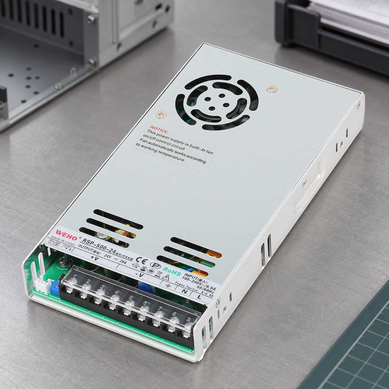
The 1 A-to-6 A step, 500 μF estimate and voltage envelope above remain hypothetical worksheet assumptions, not RSP-500-24 measurements or specifications. The product photograph identifies the intended DUT; no waveform or recovery result has been supplied. Do not derive its usable power from promotional text outside the product label.
When comparing candidates, retain the same load event and acceptance point. If local capacitance or wiring differs, record it as part of each installed configuration. Compare measured voltage/current traces and equipment behavior under those conditions, rather than selecting the smallest datasheet percentage without its test definition.
Release an event-based result
For each relevant event, save the actual current transition, minimum and maximum voltage, recovery time and equipment outcome. Identify input, load, cooling, temperature, wiring and instrument configuration. Separate a measured result from a calculation and from a manufacturer’s stated limit.
Send WEHO your load-step and voltage-envelope requirement to review an exact model. The useful request includes the load’s allowed voltage versus time, rather than only asking whether a supply has “fast response.”