



Key Engineering Takeaways
- Match the LRS-450-12 mounting-hole group to its drawing view before releasing a backplate.
- The nominal 215 × 115 × 50 mm enclosure does not define the mounting pattern; the drawing also shows 135 mm between mounting-ear hole centerlines.
- Separate M4 and M3 callouts; do not turn their printed lengths into an assumed screw-insertion limit.
- Release the hole pattern, datum and fastener requirement together after checking the applicable unit revision.
Why the Correct Size Can Still Produce the Wrong Backplate
A cabinet designer can reserve enough space for a power supply and still drill an unusable mounting pattern. The error often starts when a body dimension, a mounting-ear hole pitch and a threaded-hole spacing are copied from different views as though they described the same features.
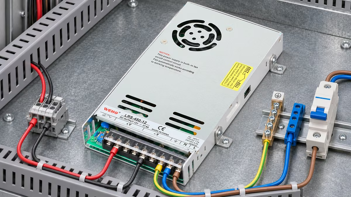
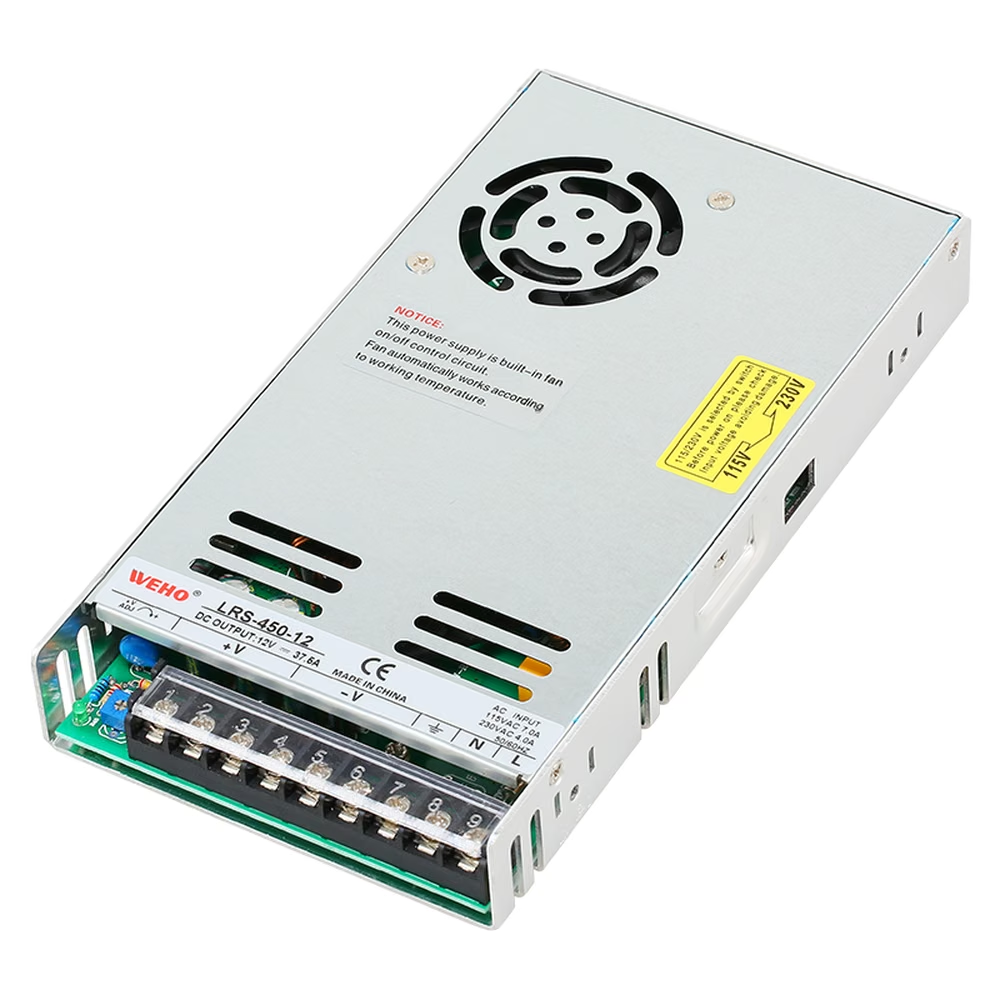
The engineering task is to identify the intended mounting group before fabricating the plate. The WEHO LRS-450-12 product page provides a useful example because its mechanical drawing contains several hole groups and two different M4 length callouts. A photograph helps identify the enclosure; the drawing and applicable installation requirements must govern the interface.
Read Each Drawing View as a Separate Set of Features
các manufacturer's LRS-450 specification lists a nominal enclosure size of 215 × 115 × 50 mm. The published mechanical drawing also shows 135 mm between the indicated mounting-ear hole centerlines. The dimension endpoints follow the hole-center reference lines; this is not the overall metal-ear envelope. These dimensions answer different questions.
A 115 mm body-width entry can help reserve enclosure space. It cannot replace the 135 mm fixing-row pitch when locating the corresponding support holes. Neither number, by itself, defines the complete drilling pattern or the overall installation envelope. The remaining hole coordinates, edge distances and the face carrying the holes still need their own information.
The drawing's plan view labels 4-M4 L=5 mm and 5-M3 L=3 mm. The side view separately labels 4-M4 L=4 mm. Keep those annotations attached to their original views and leader lines. Do not combine them into a single statement that the product has four identical M4 mounting locations with one universal insertion depth.
| Published item | What it identifies | Release question |
|---|---|---|
| 215 × 115 × 50 mm | Nominal enclosure dimensions | Which protrusions and service areas need separate allowance? |
| 135 mm between indicated ear-hole centerlines | Fixing-row pitch in the shown view | Are the matching rows located from the correct datum? |
| 4-M4 L=5 mm, plan view | A leader-defined threaded-hole group | Is this the selected mounting face and revision? |
| 5-M3 L=3 mm, plan view | A different leader-defined hole group | What purpose and attachment requirements apply? |
| 4-M4 L=4 mm, side view | The separately illustrated side group | Which fastener and permitted engagement are specified? |
The printed L values should be carried into the review record exactly as shown. They are not a substitute for a verified instruction about permitted screw penetration, engagement, tightening torque or support strength. Request clarification where those installation requirements are needed.
Build a Coordinate Record Before Copying Hole Centers
A mounting pattern becomes reproducible when every position refers to the same datum. Identify the relevant enclosure face, the viewing direction, the origin and the positive coordinate directions on the released equipment drawing. A note such as “four M4 holes” leaves these choices unresolved.
Use the power-supply drawing to identify the intended group, then transfer its dimensions through the equipment team's drawing-control process. Do not recover production coordinates by measuring pixels in a downloaded image. Page scaling, display resizing and image compression do not establish dimensional accuracy.
Consider a hypothetical fabrication review. A designer has drawn a plate for the 215 × 115 mm nominal body and selected four points that appear conveniently aligned. The drawing reviewer finds that the selected points were taken partly from an ear arrangement and partly from a threaded-hole group. The plate has enough area, but the mounting interface has not been defined.
The correct outcome is a hold on that hole-pattern release while the group is identified. Adding slots to make every possible point reachable would change the support design and still would not establish permitted screw engagement. A release decision should resolve the ambiguity rather than hide it inside a more generous cutout.
For the same hypothetical review, the difference between the shown fixing-row pitch and nominal body width is 135 − 115 = 20 mm. This compares a hole-center spacing with a body dimension. It does not establish the outer ear envelope, 20 mm of additional occupied width or 10 mm of metal projection on each side. Preserve the actual reference lines instead of turning the arithmetic into an installation envelope.
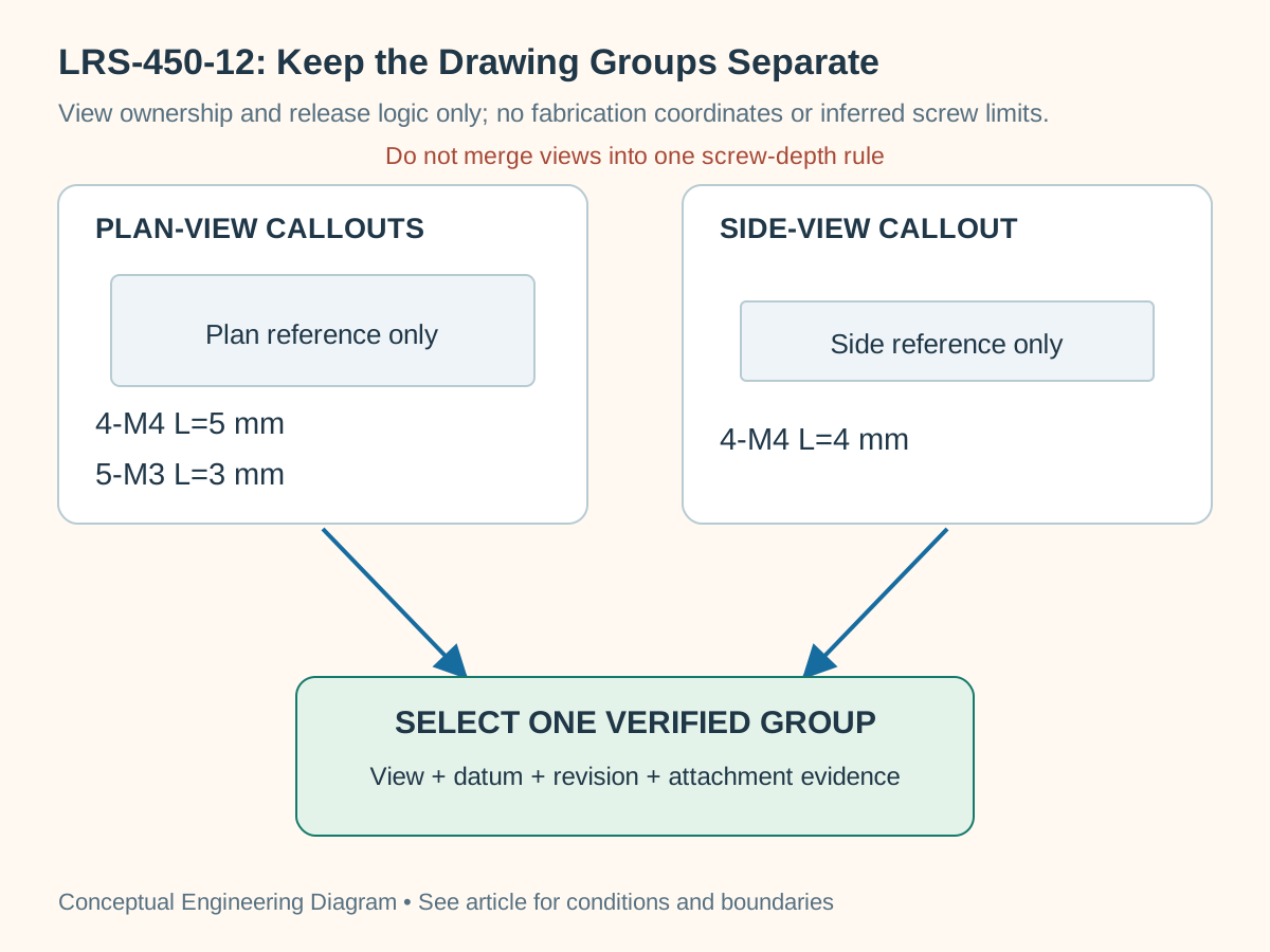
Swipe horizontally on a small screen, or open the full-size diagram.
Use a Release Matrix That Can Stop an Incorrect Transfer
The release record should distinguish a known dimension from an unresolved installation requirement. This prevents a completed spreadsheet from being mistaken for a fully approved mechanical interface.
| Release item | Required evidence | Example review outcome | Next action |
|---|---|---|---|
| Product identity | Exact model and applicable drawing revision | LRS-450-12 recorded; revision needs confirmation | Match the ordered unit to its documents |
| Mounting group | One selected face and leader-defined hole group | Mixed groups detected | Hold the transferred pattern |
| Coordinate datum | Origin and orientation on the equipment drawing | View direction missing | Add the datum and repeat the check |
| Fastener requirement | Permitted engagement and installation instructions | Printed L value only | Obtain the installation requirement |
| Physical fit | Controlled sample check against the released interface | No sample result recorded | Schedule verification before production release |
The example outcomes are review scenarios, not findings from a WEHO production test. They show how the record should produce a concrete action instead of an unexplained tick mark. Download the mounting-group release worksheet to record the selected view, source, datum and closure evidence.
Verify the Interface Without Turning the Article Into an Installation Instruction
- Identify the purchased unit. Record its full model and document revision. Confirm that the photograph and drawing describe the same mechanical arrangement before transferring dimensions.
- Select one mounting group. Mark the face and leader-defined features on a controlled review copy. Record why that group matches the proposed support; leave unrelated holes outside the transferred pattern.
- Check the drawing reference system. Compare origins, orientation and dimension chains on both documents. A second reviewer should be able to reconstruct the transfer without guessing the image's viewing direction.
- Close the fastener questions. Obtain the permitted attachment method, engagement and tightening requirements for the actual unit and support. Do not use a generic screw length merely because the thread diameter matches.
- Record physical verification. Check the released interface on a suitable de-energized sample under the equipment manufacturer's procedure. Document fit, support and access without modifying the power-supply enclosure to accommodate an incorrect plate.
A successful physical fit closes only the mechanical items it actually verifies. It does not establish protective-earth continuity, thermal performance or correct electrical connections. The separate power-supply mounting-drawing review provides a broader document checklist when other equipment interfaces are also changing.
Send WEHO the Selected Mounting Face and the Open Questions
For an LRS-450-12 mechanical review, provide the proposed mounting face, the marked hole group, your drawing revision and the specific installation requirement that remains unresolved. Include the full purchased model rather than only “450 W power supply.” Ask whether a revision-matched mechanical drawing and applicable attachment instructions can be supplied before releasing the support for production.
Engineering FAQ
Does 215 × 115 × 50 mm define the drilling pattern?
No. Those are nominal enclosure dimensions, while drilling requires the selected hole centers, mounting face and datum. The LRS-450 drawing separately identifies a 135 mm mounting-ear hole-center pitch, which must remain associated with its indicated reference lines.
Can the three threaded-hole callouts be treated as one mounting group?
No. Keep each callout attached to its drawing view and leader-defined features. Confirm which group the intended support uses, rather than combining M4 and M3 locations because they appear on the same sheet.
Does L=4 mm specify the screw length to order?
The printed annotation alone does not establish a complete fastener specification. The support thickness, permitted engagement, washers and applicable installation instructions must be resolved before choosing the ordered screw length.
Can a sample that fits replace the drawing-release record?
A sample fit supports the tested combination, but the drawing record is still needed to control repeat production and later revisions. Record which unit and interface were checked and which installation requirements remain outside that fit check.




