


| Đặc điểm kỹ thuật | LRS-450-12 | LRS-450-24 | LRS-450-36 | LRS-450-48 |
| Điện áp đầu ra DC, dòng điện | 12V 0~37.5A | 24V 0~18.7A | 36V0~12.5A | 48V 0~9.4A |
| Sóng và tiếng ồn | 150mVp-P | 180mVp-P | 240mVp-P | 240mVp-P |
| Độ ổn định của dây đầu vào | ±0.5% | ±0.5% | ±0.5% | ±0.5% |
| Tải ổn định | ±1% | ±0.5% | ±0.5% | ±0.5% |
| Hiệu quả | 82% | 85% | 86% | 87% |
| Phạm vi điều chỉnh điện áp DC | ±10% | ±10% | ±10% | ±10% |
| Dải điện áp đầu vào | 95–132VAC / 180–264VAC by switch; 254–370VDC; 47–63Hz | |||
| Tác động hiện tại | Cold start current 35A/115VAC 65A/230VAC | |||
| Bảo vệ quá tải | 105%–150% cut off the output. Protection type: Hiccup mode; recovers automatically after the fault condition is removed. | |||
| Bảo vệ quá áp | Hiccup mode with automatic recovery after the fault condition is removed. Confirm the approved overvoltage threshold for the ordered version. | |||
| Bảo vệ quá nhiệt | Turn off the output; normal output is restored after the temperature returns to normal. | |||
| Thiết lập, tăng, giữ thời gian | 1500ms,30ms/230VAC 2000ms,50ms/115VAC at full load | |||
| Chịu được điện áp | I/P-O/P:1,5kV I/P-FG:1,5kV O/P-FG:0,5kV 1 phút | |||
| Điện trở cách ly | I/PO/PI/P-FG O/P-FG: 100M Ohms/500VDC/25 ℃/70%RH | |||
| Nhiệt độ làm việc | -10oC~+50oC | |||
| Kích thước | 215×115×50mm | |||
| Cân nặng | 1kg | |||
| đóng gói | 45.5×31.5×26CM/20PCS/20kg | |||


LRS-450 Enclosed Switching Power Supply — 450W Class
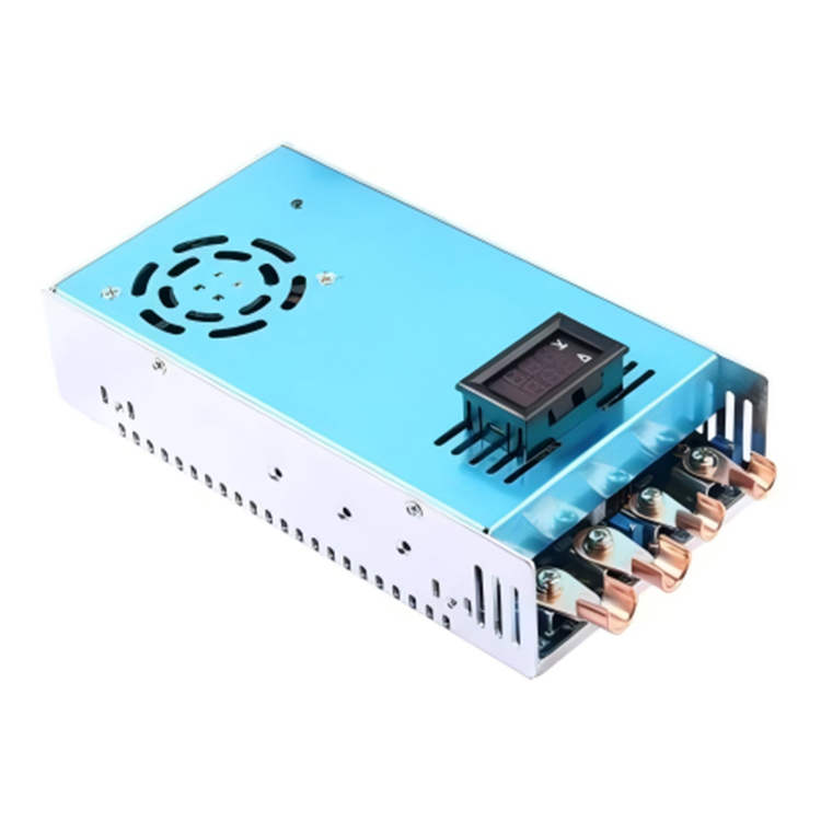
The LRS-450 is a 450W-class single-output enclosed power supply with a fan-equipped 215 × 115 × 50 mm body. Choose the 12V, 24V, 36V or 48V output version. Select 95–132VAC or 180–264VAC using the input-range switch; the DC input range is 254–370VDC and the AC frequency range is 47–63Hz. Confirm the final rated output power for the selected version with the quotation. The working temperature range is -10°C to +50°C; confirm permissible loading for the installation.
For the detailed specifications of LRS, please contact WEHO’s salespersons at E-mail: [email protected]
Gửi email cho chúng tôi [email protected]
- Sự miêu tả
Mechanical dimensions
| Body length | 215 mm |
|---|---|
| Body width | 115 mm |
| Body height | 50 mm |
| Width including mounting ears | 135 mm |
The body dimensions and mounting-hole dimensions are different references. The vector drawing below retains the dimensions printed in the WEHO original.
On a small screen, swipe the drawing horizontally to inspect every dimension. No separate drawing image or script download is required.
Load derating
Apply these curves only within the WEHO stated operating range of -10 to +50 °C and the input limits in the specification table. Observe the horizontal mounting condition. A wider reference axis does not expand the WEHO rating.
View the functional block diagram
Functional stages are shown here; the specification table governs rated output, protection thresholds and recovery.
Overview
The LRS-450 is a single-output switching power supply with documented 12V, 24V, 36V and 48V model options. For a ceramic-tile inspection bay, the 24V model is a candidate for compatible camera interfaces and sensing electronics, keeping their supply branch separate from conveyor drives. Its switch-selected AC input bands support a deliberate mains-selection step during machine commissioning. Specify the output, load profile and enclosure conditions, and confirm the continuous rating of the selected version before equipment integration.
Why Choose LRS-450?
Match the Electronics Rail, Not Just a Power Label
Four documented voltage models give the machine designer a concrete starting point for matching a local DC input. Select from those voltage and current entries rather than treating the conflicting power summary as an interchangeable rating.
Make Input Selection Part of Commissioning
The input entry specifies 95–132VAC or 180–264VAC by switch, plus 254–370VDC. A documented supply-selection check helps prevent the host equipment from being commissioned on an assumed automatic universal-input setting.
Plan the Space Around a Documented Envelope
The dimension row lists 215 × 115 × 50mm. Use that envelope to start enclosure planning, then verify mounting details, access and the installed thermal arrangement before release.
Assess Recovery Before Connecting the Machine
The sheet describes overload hiccup recovery after fault removal and output restoration after temperature returns to normal. That information supports restart planning for auxiliary electronics, but the machine safety function needs its own supply and review.
Features, Benefits & Advantages
| Tính năng | Benefit in equipment design |
|---|---|
| Four Model-Specific Output Choices | LRS-450-12 lists 12V at 0–37.5A; LRS-450-24 lists 24V at 0–18.7A; LRS-450-36 lists 36V at 0–12.5A; LRS-450-48 lists 48V at 0–9.4A. Match the equipment’s verified input to one of these four model entries and confirm the selected version’s continuous-duty rating and operating conditions before fixing the load budget. |
| Voltage Trim for a Verified Input Window | The DC adjustment row gives ±10% for each of the four models. Use adjustment only inside the connected equipment’s verified input window; it does not establish dimming or constant-current operation. |
| Separate Ripple Figures for Each Rail | The listed ripple/noise values are 150mVp-p at 12V, 180mVp-p at 24V, and 240mVp-p at both 36V and 48V. These figures are useful screening data for an inspection or measuring interface, while final signal-quality acceptance still needs the actual load and measurement method. |
| An Explicit Thermal Protection Description | The overtemperature entry says that the output turns off and normal output is restored after temperature returns to normal. Design the host controller to handle interruption and restart deliberately, rather than relying on protection as a substitute for cooling. |
Typical Service Conditions
AI LRS-series planning and application illustrations; equipment scenes are not customer-installation records or exact-model dimensional or wiring evidence.
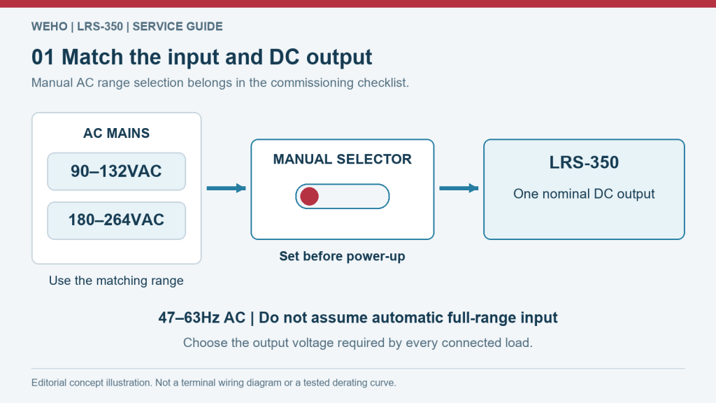
Input and load matching for LRS-450
Use the documented 95 VAC lower boundary for the low-input band, not the 90 VAC example shown in the illustration. The input row gives 95–132VAC or 180–264VAC by switch, 254–370VDC, and 47–63Hz. The documented method is switch selection, not automatic AC-range selection; verify the configured range against the host input source. Match the selected DC version to every connected input, then include simultaneous demand and startup transients before energising the equipment. The planning image is a representative LRS-series example, not an exact-model wiring diagram.
LRS-350 manual-selector planning example; use LRS-450 input bands, selection instructions and output options, not the example labels.
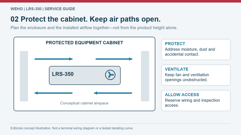
LRS-450 enclosure and service-space planning
The dimension row gives 215 × 115 × 50mm and weight is 1kg. The withstand row lists I/P–O/P 1.5kV, I/P–FG 1.5kV and O/P–FG 0.5kV for one minute. Reserve additional space for terminal access, conductor routing and the host equipment's airflow; the case outline is not a clearance allowance.
LRS-series cabinet-space concept; the exact case, cooling method and mounting are defined by this model's own technical data.
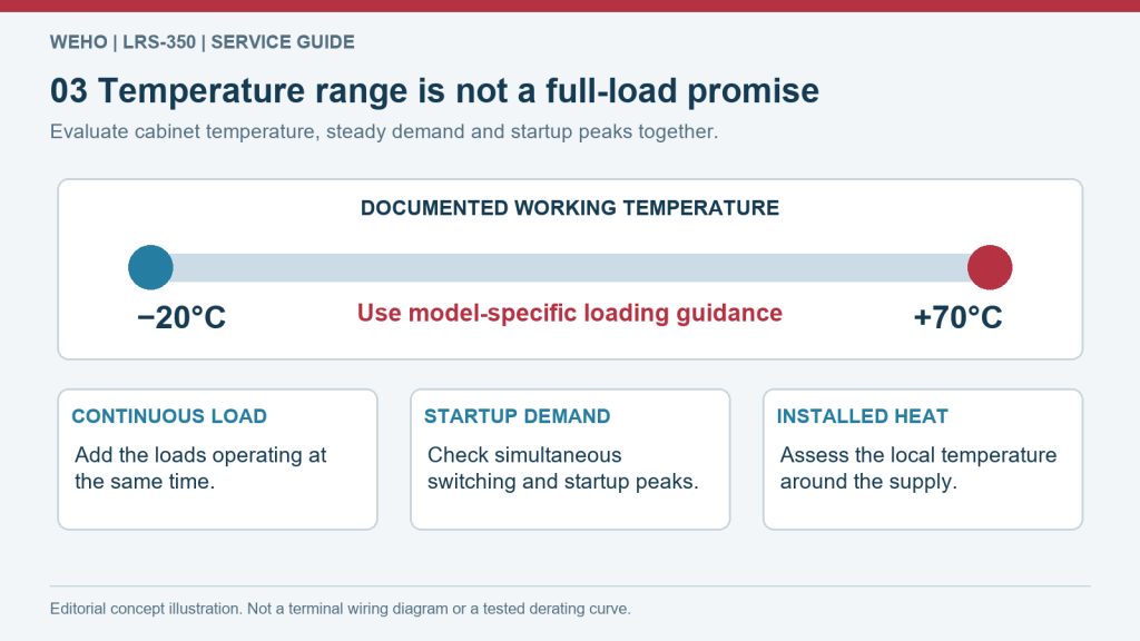
Temperature and duty-cycle assessment for LRS-450
For LRS-450, use its −10°C to +50°C working-temperature row; the illustration's −20°C/+70°C labels are not this model's rating. The working-temperature row states −10°C to +50°C. Use the temperature/load curve displayed with the model-specific technical data under its stated conditions. Measure the temperature at the installed supply and review the longest expected duty cycle. Keep vents unobstructed; do not substitute room temperature for the operating temperature inside the equipment.
LRS-350 temperature-planning example, not a measured derating curve or a replacement for LRS-450 operating limits.
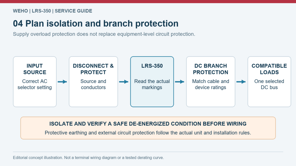
LRS-450 fault recovery and protected installation
Overload is listed as 105–150%, cutting off the output in hiccup mode with automatic recovery after fault removal. Overtemperature protection turns off the output and restores normal output once temperature returns to normal. Have a qualified installer check terminal identification, protective earthing and branch protection for the actual assembly. Coordinate restart behaviour with the equipment controls rather than treating supply recovery as a safety function.
Functional power-planning illustration only; follow the exact model's terminal identification and qualified installation instructions.
Application Industries
AI LRS-series planning and application illustrations; equipment scenes are not customer-installation records or exact-model dimensional or wiring evidence.

Retail sign-control and LED-module branches
In a retail lightbox, consider LRS-450 for a defined compatible lighting-control or module group after confirming the selected version’s continuous rating and thermal conditions. Keep any LED current-control stage separate. The scene does not resolve the datasheet’s differing power-summary wording.
Conditional output example: LRS-450-24 (24V).
AI application concept — retail signage, not an installation record for this product.
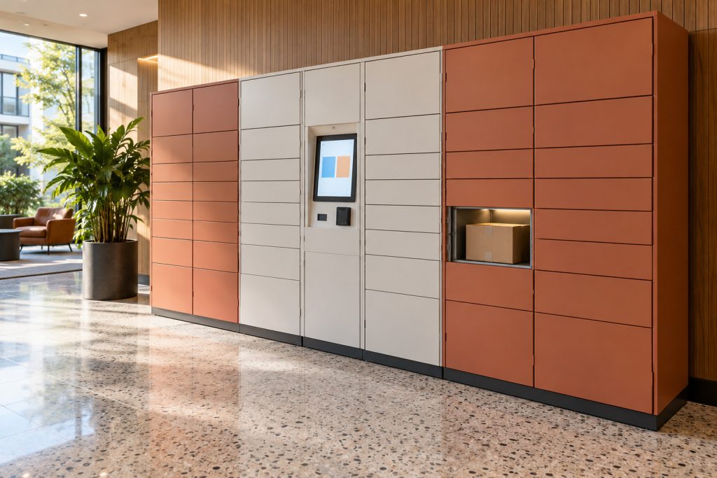
Parcel-terminal interface electronics
For a locker bank, assess LRS-450 against the ordered voltage version, controller load and the planned door-release combinations. Verify the continuous rating before fixing the distribution budget. Display power, redundancy and backup charging are separate requirements, not implied features.
Conditional output example: LRS-450-24 (24V).
AI application concept — parcel-terminal electronics, not an installation record for this product.
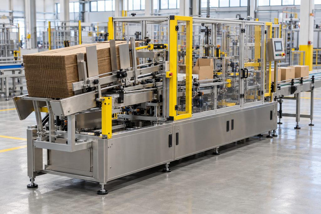
Carton-packaging auxiliary electronics
At a carton-forming station, a compatible LRS-450 branch may serve sensing and control interfaces while the drive system uses its own supply. Include simultaneous electronics and coil demand, and coordinate restart behaviour. The machine safety function remains separate from hiccup recovery.
Conditional output example: LRS-450-12 (12V).
AI application concept — carton-packaging auxiliary electronics, not a complete-machine power claim.
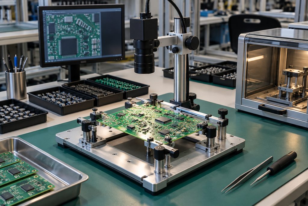
Electronics-fixture auxiliary interfaces
A PCB fixture may use an appropriately qualified LRS-450 branch for controller and interface electronics. When the selected rail exceeds their input window, specify a suitable converter rather than connecting the devices directly. DUT power and precision excitation remain outside this auxiliary role.
Conditional output example: LRS-450-48 (48V) at a separately qualified downstream converter input; the converter must provide the required electronics rail.
AI application concept — electronics-fixture interfaces; no measurement-performance or installed-model claim.
Câu hỏi thường gặp
Which LRS-450 output models are documented?
The model row lists LRS-450-12, LRS-450-24, LRS-450-36 and LRS-450-48. Their respective output entries are 12V 0–37.5A, 24V 0–18.7A, 36V 0–12.5A and 48V 0–9.4A. This sheet does not document a 15V column.
Does the LRS-450 sheet establish a continuous 450W or 500W rating?
The page header identifies LRS-450W and the table identifies LRS-450 models, but the summary reads “Single output: power 500W”. That internal conflict does not establish either 450W or 500W as the continuous rating for the selected model. Retain the documented voltage/current entries and obtain manufacturer clarification of the power basis and operating conditions; multiplying voltage by maximum listed current is not a replacement rating.
What input bands and selection method are specified?
The input row gives 95–132VAC or 180–264VAC by switch, 254–370VDC, and 47–63Hz. The documented method is switch selection, not automatic AC-range selection; verify the configured range against the host input source.
What DC voltage adjustment is listed?
All four LRS-450 columns list ±10% adjustment. Adjustment is not evidence of constant-current control, dimming or compatibility with a load outside its specified input window.
What ripple/noise figures apply to the four outputs?
In 12V, 24V, 36V and 48V order, the figures are 150mVp-p, 180mVp-p, 240mVp-p and 240mVp-p. Bandwidth, probing and complete test conditions are not stated on this page, so these figures alone do not establish instrument-level performance.
How do the line and load stability entries differ?
Inlet-wire stability is ±0.5% for every output; load stability is ±1% for 12V and ±0.5% for 24V, 36V and 48V. Those row labels do not specify the dynamic response of the connected machine.
What efficiency is printed for each LRS-450 model?
The 12V, 24V, 36V and 48V columns list 82%, 85%, 86% and 87% respectively. The page does not provide complete efficiency test conditions or a load-efficiency curve.
What overload and overtemperature behaviour is described?
Overload is listed as 105–150%, cutting off the output in hiccup mode with automatic recovery after fault removal. Overtemperature protection turns off the output and restores normal output once temperature returns to normal. These descriptions do not qualify motor starting, heater control or a machine safety circuit.
Why is no voltage threshold derived from the overvoltage row?
Under “Overvoltage protection”, the sheet states “115%~135% rated output power” and describes hiccup recovery after fault removal. The power wording and voltage heading leave the threshold basis unresolved; a voltage percentage or threshold in volts requires separate manufacturer confirmation.
What timing values and full-load conditions are actually printed?
The timing row prints 1500ms and 30ms at 230VAC, and 2000ms and 50ms at 115VAC, with “at full load”. Although its heading names setup, rise and hold-up, only two values per input are given, so a separate hold-up duration is not identifiable.
Does the −10°C to +50°C range permit full load at every temperature?
The working-temperature row states −10°C to +50°C. Use the temperature/load curve displayed with the model-specific technical data under its stated conditions. The operating interval alone is not a promise of full output at every temperature. Assess mounting, airflow, actual load and temperature in the finished equipment; the reference curve does not expand the WEHO model's stated operating or output ratings.
What mechanical and electrical-isolation data are available?
The dimension row gives 215 × 115 × 50mm and weight is 1kg. The withstand row lists I/P–O/P 1.5kV, I/P–FG 1.5kV and O/P–FG 0.5kV for one minute. Isolation resistance is listed as 100M Ohms at 500VDC, 25°C and 70%RH for the stated paths. These sheet entries do not establish an ingress rating, certification scope or final host-equipment acceptance.


Sản phẩm Power Supply nào tốt nhất cho doanh nghiệp của bạn?
Thúc đẩy hoạt động kinh doanh của bạn với các sản phẩm bộ nguồn chất lượng WEHO.
Hỏi chuyên gia