

Key Engineering Takeaways
- An SSR can fail with its load path conducting after the controller commands OFF.
- Compare the actual heater current with the control command; a dark output indicator does not prove energy removal.
- Hazardous overheating requires a separately engineered protective function that can interrupt heater energy despite the failed SSR.
- Validate detection, interruption, residual heat and reset behavior together; an alarm message alone is insufficient.
Define the failed-switch condition before changing PID settings
Persistent heater current during a genuine OFF command is a different problem from poor PID tuning. First establish which command reached the switching device and what current actually flowed through the heater branch. An incorrectly mapped output, a wiring path around the SSR and a failed semiconductor can produce superficially similar symptoms.
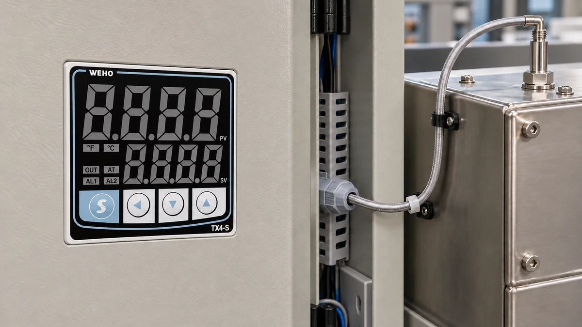
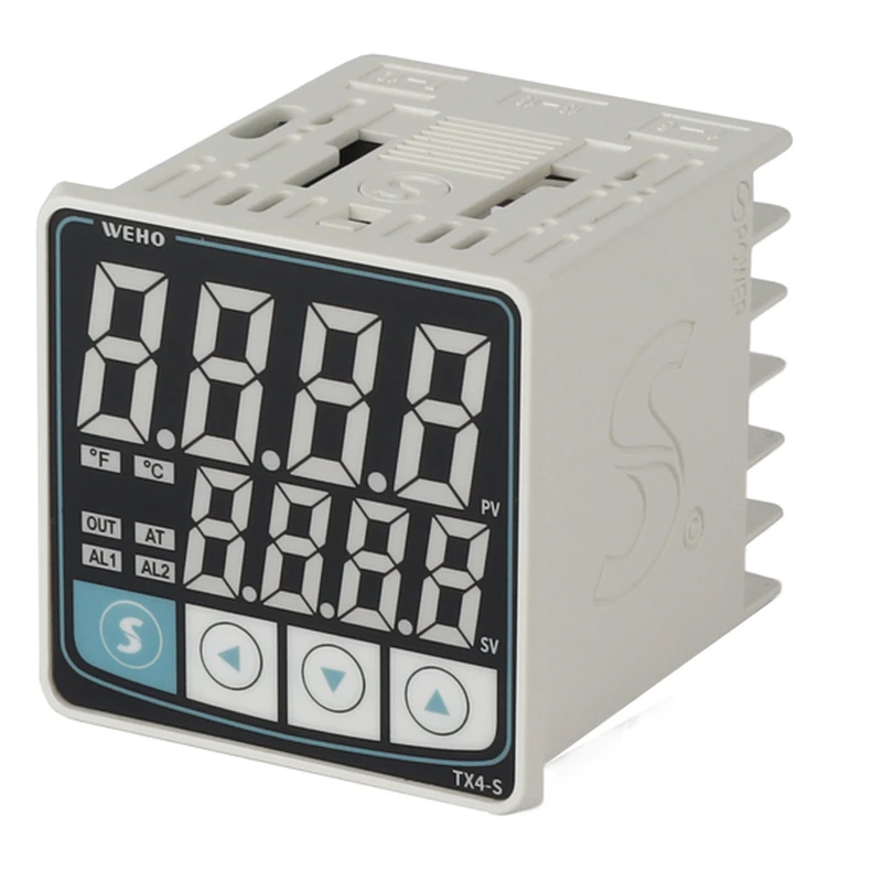
ال WEHO TX4-S temperature controller is a process-control product reference for this discussion. Match the complete received configuration to its instructions. Its display, alarm settings and selected output mode do not by themselves establish an independent high-limit protective function.
OMRON's SSR precautions identify short-circuit failure as a principal SSR failure mode and describe using another suitable switching device to remove load power if the SSR fails. The selection and architecture of that protective path belong to the machine's electrical and safety design; this article does not provide a construction circuit.
Separate command, current and temperature evidence
A controller's OFF indication reports the controller's state. A measurement at the SSR input reports the command presented to the SSR. A heater-branch current measurement reports electrical energy flow through the observed path. Temperature reports the thermal response at the sensor location. Retain these observations on a common timeline so their relationship can be examined.
A rising temperature after OFF does not automatically prove an SSR fault. Heat stored in the element and nearby structure can continue moving toward the measured location. Conversely, a stable displayed temperature does not prove that a hidden heater branch has stopped taking power. Use the full evidence set rather than selecting whichever signal fits the initial diagnosis.
| Control command | Heater current | Observed condition | Evidence needed |
|---|---|---|---|
| ON | Expected current present | Possible normal heating | Correct branch, load and thermal response |
| ON | Unexpectedly absent | Open load or interrupted supply path | Source, wiring and heater continuity review |
| OFF | Above the validated OFF allowance | Command/current disagreement | Actual SSR input, current waveform and alternate paths |
| OFF | Within the validated OFF allowance | Electrical OFF condition at observation point | Residual heat and other energy sources |
OMRON's temperature-controller terminology distinguishes SSR failure detection, based on current while the command is OFF, from heater burnout detection, based on missing current while ON. That diagnostic principle does not establish that a particular TX4 configuration contains a current-transformer input or either diagnostic feature.
The permitted OFF current and observation interval must come from the actual SSR, monitoring equipment and process design. Snubber paths, switching behavior and measurement limitations affect interpretation. A handheld reading without the command state and sampling conditions cannot establish the required failure response.
Specify an interruption path that survives the failed SSR
Sending another OFF command to a shorted SSR does not restore its blocking function. Define a protective path capable of interrupting the relevant heater energy independently of that failed switching element. Review the sensing, decision and final interruption functions together, including their supplies and shared failure paths.
ال TX4 instruction manual, 230808EN calls for a fail-safe device when controller use in machinery could cause severe injury or substantial economic loss. That requirement is not a declaration that every external alarm relay arrangement meets it. The responsible designer must determine the protective requirements for the actual equipment and applicable standards.
The existing TX4 alarm and external interlock article addresses alarm events and their interface boundaries. The additional decision here is whether heater energy can still be removed when the normal output switch has failed conducting, and whether the complete shutdown reaches the required thermal outcome.
Review common dependencies explicitly. Two functions reading the same damaged process sensor may share an undetected error. Two commands acting only on the same failed SSR share the failed interruption point. Calling a second software condition “high limit” does not establish independence; document which failures the protective path must tolerate and how that is verified.
Work through a hypothetical shutdown review
Assume a hypothetical resistive heater receives 230 V RMS and 8.0 A while conducting. For this simplified unity-power-factor example, the electrical input is:
Heater power = 230 V × 8.0 A = 1,840 W.
Assume the normal controller has commanded OFF but a failed switching path continues supplying that power for another 3.0 seconds before an independent device removes it. The additional electrical energy is:
Additional input energy = 1,840 W × 3.0 s = 5,520 J.
The 3.0-second interval is an illustrative assumption, not an acceptable shutdown-time recommendation or a TX4 response specification. The calculation shows why detecting an alarm and actually interrupting power are separate events. It cannot predict the final process temperature without a validated thermal model or appropriate test evidence.
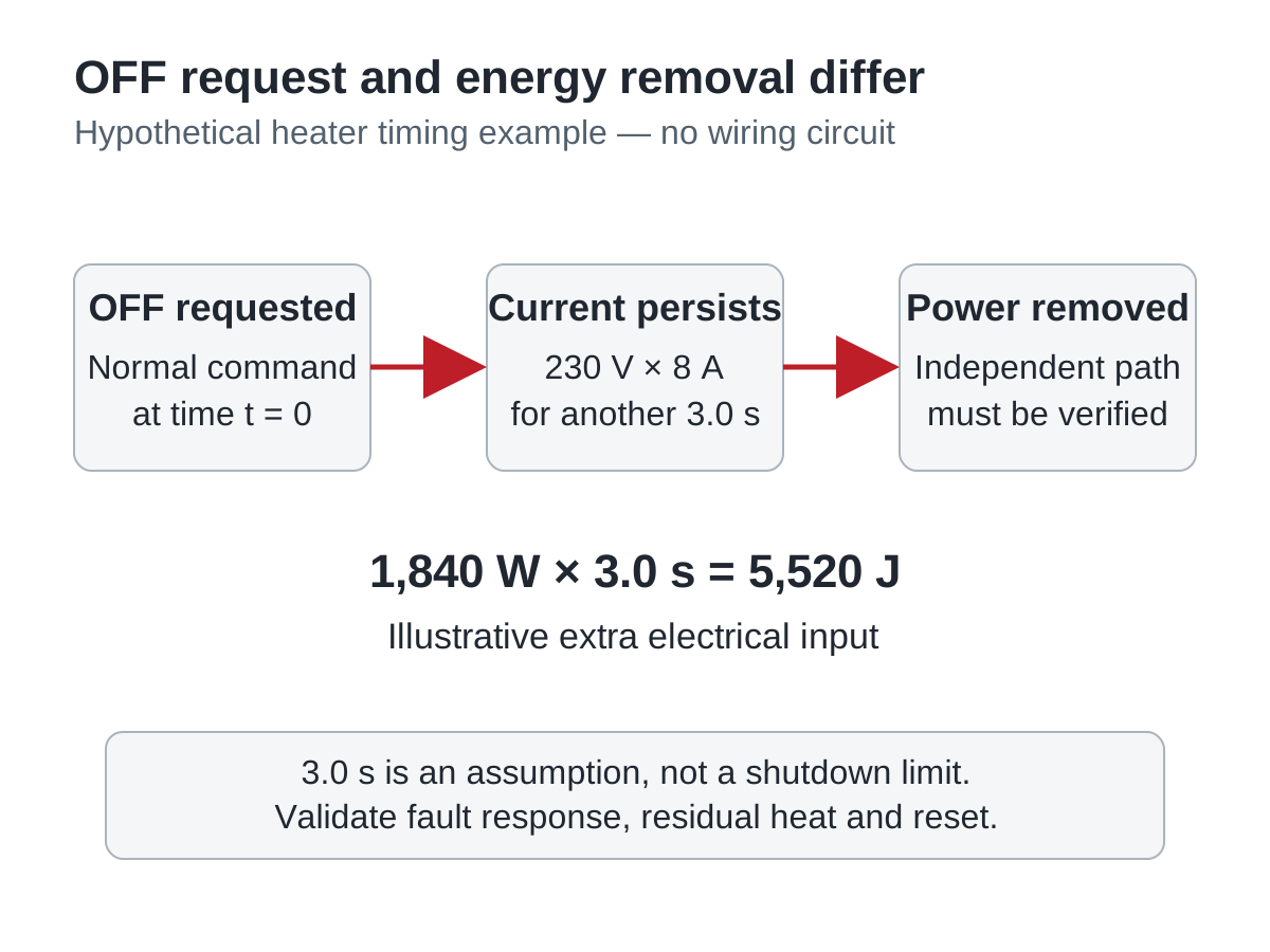
Swipe horizontally on a small screen, or open the full-size diagram.
Complete the hypothetical decision record as follows: the OFF command is defined, the continuing current is observable, and an interruption concept exists. Release remains on hold if the detection interval, interruption performance, residual thermal overshoot or reset behavior has not been demonstrated against the equipment's protective requirements.
| Record item | Hypothetical evidence | Release question | Disposition |
|---|---|---|---|
| Command/current disagreement | OFF request with continuing branch current | Are observation and detection limits validated? | Verify monitoring method |
| Independent interruption | Separate interruption device proposed | Can it remove all relevant heater energy after SSR failure? | Verify architecture and ratings |
| Thermal consequence | 5,520 J illustrative extra input | Does the actual process stay within its protective limit? | Hold without thermal evidence |
| Restart | Reset behavior unspecified | Can reset or power restoration cause unwanted reheating? | Hold until behavior is defined |
Validate the protective response without creating an uncontrolled fault
Qualified personnel should use the equipment's documented, controlled validation method. A manufacturer-supported simulation, isolated functional test or appropriately engineered test fixture can evaluate a required condition without deliberately creating an uncontrolled short circuit in operating equipment. Record what the method actually exercises and which failure modes it cannot prove.
- Define the hazardous condition. Record the heater zone, affected material, protective temperature limits and all energy sources. Verify that the specified sensing location and response requirement address the real thermal hazard.
- Identify every interface. Record the exact controller configuration, SSR, monitoring method and final interruption device. Verify their functions and ratings from their own instructions, including the applicable TX4-S configuration information.
- Check command/current disagreement. Record the test stimulus, command state, measured branch current and detection timing. Verify the diagnostic against its documented allowance and observation window rather than an arbitrary zero-current rule.
- Check energy removal and thermal response. Record the interruption event, remaining energy paths and temperature history. Verify the required protective outcome, including post-interruption heating and the consequences of a failed normal sensor where relevant.
- Check reset and restoration. Record acknowledgement, fault clearance, reset, controller restart and restoration of each supply. Verify that the machine cannot resume hazardous heating merely because an alarm clears or power returns.
Retain configuration revisions with the results. Changing heater power, thermal mass, sensor location, SSR type or the interruption device can affect the validated response. A replacement matching only the controller's panel dimensions does not preserve the entire protective function.
Send the failure-response requirement with the controller enquiry
Ask WEHO for the applicable TX4 configuration and instruction details for the process-control interface. Include heater type, switching arrangement, command signal and the independently engineered protective requirements. Identify any requested diagnostic or isolation feature explicitly so availability can be confirmed for the exact ordered unit; do not assume a standard process controller supplies the machine's safety function.
Engineering FAQ
Does a dark controller output indicator prove the heater is off?
No, the indicator alone does not prove heater energy has stopped. Establish the command at the switching interface and observe current in the relevant branch. A shorted SSR or a separate wiring path can leave the load energized after the controller requests OFF.
Will reducing the PID output stop a shorted SSR?
Reducing the command cannot guarantee interruption through a shorted SSR. The failure-response design needs another suitable way to remove the relevant heater energy. Investigate the actual command and current before treating persistent heating as a tuning problem.
Is SSR failure detection the same as heater burnout detection?
No, the two diagnostics evaluate opposite command/current mismatches. SSR failure detection looks for unexpected current during OFF; heater burnout detection looks for missing current during ON. Availability, thresholds and timing depend on the actual monitoring product.
Can the normal TX4 alarm replace an independent high-limit system?
That substitution requires evidence for the complete protective function. A process alarm setting or relay label does not establish the necessary independence, fault behavior or safety performance. Use the exact controller documentation and the machine's protective requirements to assess the proposed arrangement.
Why can temperature continue rising after heater power is interrupted?
Stored heat can continue moving into the measured process after electrical interruption. Validate the thermal response at the relevant location and under representative operating conditions. Electrical shutdown time alone cannot establish that the process remains below its protective limit.