



Key Engineering Takeaways
- The WHP-300 product page lists a separate USB output of 5 V, 1 A.
- The inverter's 300 W AC rating does not define the USB port's capacity.
- Compare peripheral voltage, current and interface requirements, including startup demand.
- Verify the complete port, cable and receiving-device combination before release.
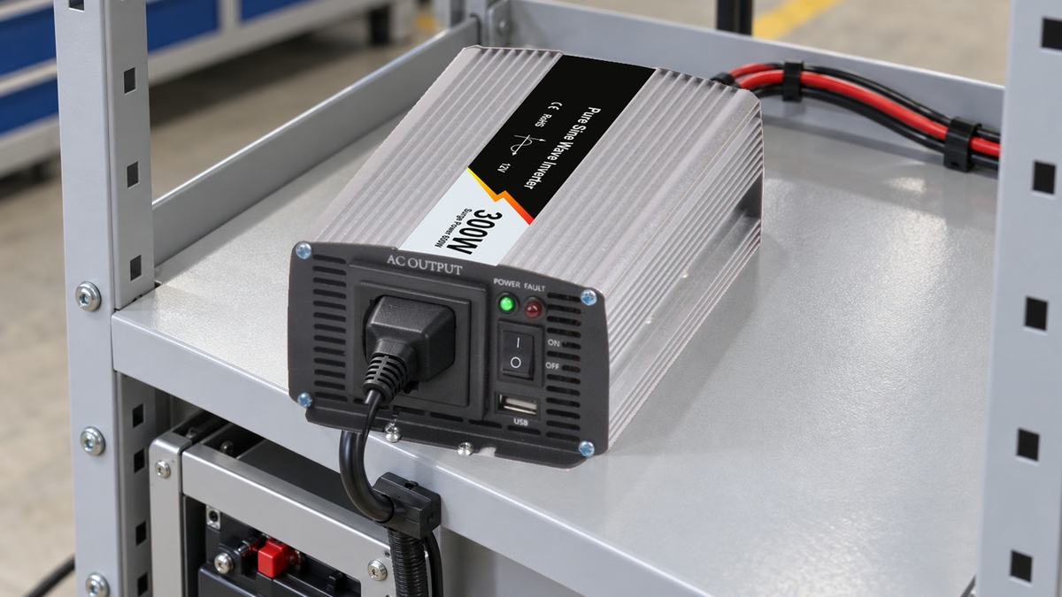
Why does a 300 W inverter need a separate USB check?
The USB port is a different output from the AC socket. A buyer cannot use the inverter's AC wattage to approve a USB-powered instrument, logger or commissioning accessory. The decision needs the low-voltage port rating and the actual receiving-device requirements.
ال WHP-300 inverter output information lists 300 W rated AC power and a 5 V, 1 A USB port. For an OEM assembling a mobile inspection or service kit, treat those as separate electrical boundaries. The photographed 12 V input version also needs its own correct DC supply arrangement.
This article evaluates a peripheral power path. It does not establish suitability for a named instrument or promise a USB charging protocol that the available product information does not identify.
What does the published USB rating establish?
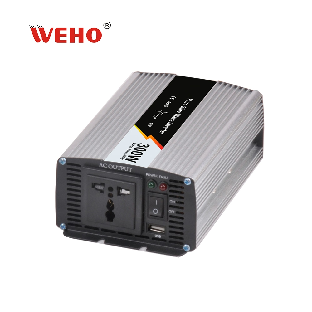
ال WHP-300 product PDF identifies the USB output alongside the AC socket and power switch. Together with the current product table, it provides a 5 V, 1 A starting point for the port-power review.
At the stated voltage and current, the electrical product is:
Port power = 5 V × 1 A = 5 W.
That arithmetic does not identify a negotiated charging profile, a voltage tolerance, an allowable overload duration or a guaranteed response to a particular device. Do not add USB-PD, Quick Charge or other protocol claims without applicable documentation.
A connector that physically accepts a cable is only one part of compatibility. The receiving device may need a defined source interface as well as sufficient nominal voltage and current. Obtain its power requirements and compare them with the actual port configuration supplied with the ordered inverter.
How should a peripheral current budget be built?
Start with the device's required operating states rather than one convenient average. Booting, display brightness, communication activity, charging an internal battery or powering an attached accessory can change demand. Use the receiving-device documentation and appropriate observations to identify the relevant states.
A Hypothetical Peripheral-Power Example illustrates the comparison. Assume one accessory specifies 5 V and draws 0.65 A during a defined steady operating condition. Its illustrative power is 5 V × 0.65 A = 3.25 W. The current lies below the published 1 A port rating for that stated condition.
Now assume the same accessory requires 1.2 A during startup. At 5 V, that demand is 6 W and exceeds the stated 1 A current. The lower steady demand does not establish that startup is supported. No transient overload capability should be inferred from the inverter's much larger AC peak-power figure.
These numbers are invented examples, not WHP-300 or accessory test results. A compatible operating point also needs acceptable voltage at the receiving device, the correct interface and the required behavior through the intended equipment sequence.
| Hypothetical condition | Demand at 5 V | Comparison with 1 A | Remaining question |
|---|---|---|---|
| Defined steady operation | 0.65 A; 3.25 W | Below the stated current | Receiver voltage and interface compatibility |
| Illustrative startup | 1.20 A; 6.00 W | Exceeds the stated current | Do not assume an overload allowance |
| Unspecified operating state | Unknown | No valid comparison | Obtain maximum relevant demand |
The result is a shortlist decision, not a complete compatibility approval. A device can have a modest average demand while presenting an unsupported starting condition. Conversely, a published maximum needs its operating conditions before it can be compared fairly.

Swipe horizontally on a small screen, or open the full-size diagram.
Why must the cable and receiver voltage be included?
The receiving device operates at the far end of a real cable and connector path. Resistance in that path can reduce the delivered voltage as current rises. The nominal 5 V source label does not establish the voltage available at the accessory during its most demanding state.
Use the intended cable and connection arrangement for verification. A shorter laboratory lead does not qualify an extended service-kit cable. Record the cable identification, connectors, operating state and observed voltage at the receiving device, then compare the result with that device's documented input requirement.
Avoid assigning a universal acceptable voltage drop from the nominal rating alone. The accessory's permitted voltage range, source behavior and actual current determine the relevant comparison. An observation at no load is insufficient when the concern occurs during boot or another high-demand state.
The cable check also has a configuration purpose. A replacement lead or intermediate accessory can change the path that was evaluated. Keep the released cable arrangement with the approved peripheral list rather than allowing unspecified substitutions.
How should the complete power path be verified?
- Identify the ordered WHP-300 input/output configuration and confirm the actual USB port rating. Match the product documentation to the unit rather than inferring every option from a family photograph.
- Obtain the peripheral's voltage, maximum relevant current and source-interface requirements. List the operating states that can change demand.
- Compare demand with the published port limit before connecting the proposed combination. An over-limit example needs another supported arrangement or further applicable supplier information.
- Verify the intended port, cable and device under the equipment commissioning procedure. Record device startup, steady operation and the relevant changes in demand.
- Observe receiving-device voltage and behavior. Record resets, incomplete startup or other deviations without declaring the cause from the symptom alone.
- Keep the accepted configuration and any unresolved conditions with the kit bill of materials. Recheck affected conditions after changing the peripheral, cable or source revision.
Use the correct equipment and qualified personnel for electrical measurements. The USB review does not qualify the inverter's DC input installation or AC distribution; those paths require their own documented design and verification.
What if several devices are proposed?
A single published port rating does not establish a multi-device distribution design. An intermediate hub or splitter has its own power-path behavior and compatibility requirements. Do not infer independent current allowances from the number of cable branches.
If a project needs several accessories, specify the actual distribution arrangement and determine whether each device is powered from that port or from another qualified source. Account for simultaneous startup and operating demand without assuming that a low combined average guarantees operation.
Return to the WHP-300 USB and AC ratings when documenting the boundary. The useful distinction remains between one low-voltage port and the separate AC output. Neither rating should be silently used as the capacity of the other.
What should be sent for a product review?
Use the USB peripheral power worksheet to record the accessory, operating states, required interface, intended cable and observations. Keep supplier specifications separate from actual measurements and identify any current requirement that remains unknown.
Send WEHO the WHP-300 peripheral requirements, including the exact inverter configuration and proposed receiving device. Ask for applicable port/interface information and any relevant operating restrictions. Keep the complete kit compatibility decision with the OEM responsible for its intended use.
Engineering FAQ
Can the 300 W AC rating support a 10 W USB device?
The AC rating does not establish USB capacity. The cited WHP-300 USB specification is 5 V, 1 A, equivalent to 5 W at those stated values. Compare the actual USB demand with that separate port rating.
Does a USB connector prove fast-charging support?
A physical connector does not establish a charging protocol. The cited product information does not identify USB-PD or another fast-charging profile. Obtain the applicable interface information for the delivered configuration.
Is a low average current enough to approve a device?
A low average does not establish startup or maximum-demand compatibility. Check the operating states that matter to the accessory and avoid assuming a transient overload allowance that the source documentation does not provide.
Should a replacement cable be checked again?
Recheck the affected power path when the cable or connection arrangement changes. Receiver voltage and operating behavior depend on the complete source-to-device path, not only the nominal source label.



