



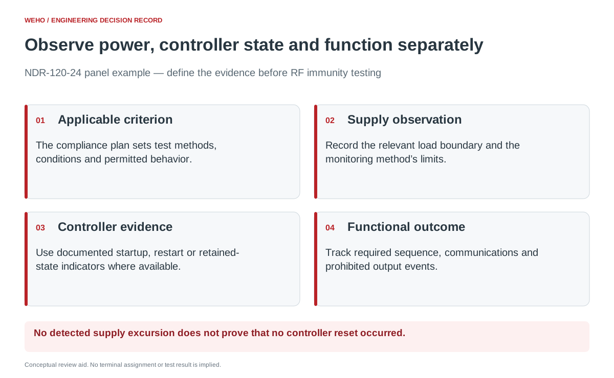
Before RF immunity testing, define which controller events count as a reset, how they will be detected, and what functional behavior the equipment must maintain. A power-supply indicator alone cannot show whether an attached controller rebooted, lost data or briefly changed an output.
This article gives a controls engineer an acceptance-record structure for a panel using an NDR-120-24 supply candidate. It does not claim that this supply or a completed panel has passed a particular RF exposure level.
Separate the RF test plan from the functional acceptance plan
IEC 61000-4-3:2020 provides a common method for radiated RF electromagnetic-field immunity. IEC 61000-4-6:2023 addresses conducted disturbances induced by RF fields. The two standards address different test mechanisms; a report for one is not automatically evidence for the other.
Both are basic EMC publications. Their public scopes explain that the relevant product committees determine applicability, levels and performance criteria. Have the responsible compliance engineer and laboratory identify the applicable product requirements, editions, exposure conditions and operating modes. Do not copy a test level from another machine’s report.
The functional acceptance plan complements that laboratory plan. It says what the panel must do, how the observer will know, and which events trigger a recorded nonconformity or engineering review.
Use the NDR-120-24 as a supply candidate, not an RF certificate
ال WEHO NDR-120 product page و NDR-120 specification sheet list the NDR-120-24 as a 24 V, 5 A model. That identifies its output role in the panel. It does not establish a completed panel’s RF immunity, nor an unsupported RF test level for the supply.
Request any applicable exact-model EMC reports and their conditions when available. Record the tested construction, ports, loads and restrictions before deciding what the report covers. A generic compliance row cannot substitute for that evidence.
Panel behavior also depends on the controller, interfaces, enclosure and complete cable arrangement. The IEC 61000-4-3 public description notes the importance of a reproducible equipment and cable configuration. Keep the released test configuration with the observations so a later comparison has meaning.
Define a reset in terms of observable controller evidence
Write the normal operating sequence and the indicators that distinguish continuation from restart. Depending on the actual controller, useful evidence may include its documented startup event, uptime value, restart counter or retained event log. Confirm those signals exist and what they mean; do not assume every PLC offers the same diagnostics.
Use a separate functional observation for the machine task. A communications gap is not automatically a controller reset, and a controller that resumes scanning may still have lost a recipe or command state. Give each event a distinct classification.
| Observation channel | Acceptance question to define | Record with the event |
|---|---|---|
| Supply at the relevant load boundary | Did the monitored supply condition remain within the project’s requirement? | Instrument method, location and time alignment defined by the test team. |
| Controller execution state | Did startup, watchdog recovery or another defined restart event occur? | Documented event code, restart indicator or equivalent trace. |
| Communications and stored data | Were required communications, settings and retained values maintained? | Affected channel, duration and before/after state. |
| Controlled function | Did the commanded task remain correct and avoid prohibited output behavior? | Expected sequence and the independently observed outcome. |
The test engineer should choose monitoring that does not invalidate the EMC setup or conceal events. Establish a baseline with the same observation channels before RF exposure. Do not call an unobserved interval a pass.
Set event rules before reviewing the results
For each required operating mode, define permitted temporary degradation, required recovery and prohibited behavior using the applicable product criteria and the equipment requirements. State whether operator intervention, an automatic restart or loss of retained data is allowed. The answer depends on the equipment; it is not a universal rule supplied by the power-supply wattage.
A useful mode matrix might cover normal cyclic operation, a required communication exchange and an authorized standby-to-run transition. Select modes that represent the actual equipment function rather than exercising a visually impressive but irrelevant load.
Tie every recorded event to the laboratory test reference and synchronized time record. Where a monitoring channel cannot capture a short interruption, document that limitation and resolve the missing coverage before claiming that no reset occurred.
A hypothetical event can fail the function while the supply appears normal
Imagine a panel whose requirement prohibits automatic restart during a production sequence. Its supply observation shows no detected excursion within the method’s recorded resolution, but the controller’s startup counter increases and the sequence restarts. This is a hypothetical classification example, not an NDR-120-24 result.
The restart is evaluated against the prohibited-event requirement even though the supply channel appears normal. It also does not prove the supply caused the event. Preserve the traces and configuration; the engineering investigation can then examine the relevant controller, power and interface paths.
Conversely, if a communication interruption occurs without a documented startup event, classify it as the observed communication event. Do not inflate a symptom into a reset diagnosis or erase it because the controller did not reboot.
Keep the acceptance record usable after a component change
The final record should identify the applicable criterion, tested mode, observation coverage, actual event and disposition. Retain the supply version, controller firmware, configuration and laboratory report reference with it. Separate a completed test from an investigation still awaiting a repeat run.
When changing the supply or another panel component, ask the responsible compliance engineer what evidence or repeat testing the change requires. A statement that both supplies are 24 V does not establish that the tested system configuration remains represented.
Use the project record
Open the blank Control Panel RF Immunity — Functional Event Record to record your conditions, evidence and decisions. The worksheet contains no pre-approved result.
Request NDR-120-24 information for the test configuration
Send WEHO the exact model and revision you intend to use, your panel application and the model-specific EMC evidence requested by your compliance engineer. Keep the final functional criteria and laboratory configuration under the panel owner’s control.




