Do not divide total DC current equally between parallel conductors unless the complete path resistances justify that assumption. Calculate the parallel combination, include contact and return-path resistance, then check the voltage and current in credible unequal or unavailable-path states. A satisfactory nominal voltage-drop result does not establish conductor ampacity, terminal suitability or fault protection.
On this page
This guide concerns multiple conducting paths from one DC source to a load. It does not approve paralleling power-supply outputs. It uses stated resistance values rather than selecting a wire size or interpreting installation rules.
Define where the paths split and rejoin
Identify the two common nodes of the parallel section. Each path resistance must include the relevant conductor, connector and contact contributions between those nodes. Anything shared before the split or after the join carries total current and must be accounted for separately.
A cable-length comparison alone can miss unequal terminations or a shared return. Record whether each resistance is a supplier value, an estimate or a measurement, and at what temperature and condition. A milliohm figure without its boundary is easy to use twice or omit from the loop.
OpenStax’s series and parallel resistance treatment establishes the calculation basis: parallel paths have the same voltage across their common nodes, while their currents depend on resistance. Current divides inversely with resistance, and the individual currents add to the total.
Worked example with two unequal outbound paths
Assume a source remains exactly 24.00 V at its output terminals and the load draws a fixed 10.00 A. The outbound paths connect the same two nodes. Path 1 is 0.040 Ω and path 2 is 0.060 Ω, including their respective contacts. A shared return adds 0.030 Ω. These are hypothetical complete-path resistances, not cable recommendations.
The outbound equivalent is R = (0.040 × 0.060) ÷ (0.040 + 0.060) = 0.024 Ω. Its drop is 10.00 A × 0.024 Ω = 0.240 V. Path currents are 0.240 ÷ 0.040 = 6.00 A and 0.240 ÷ 0.060 = 4.00 A. Assigning 5 A to each path would contradict the assumed resistances.
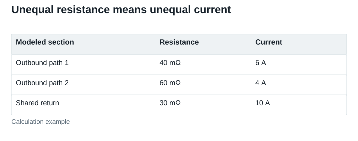
The return drop is 10.00 A × 0.030 Ω = 0.300 V. Total modeled loop drop is 0.540 V, leaving 23.460 V at the load. The return cannot be halved merely because the outbound side contains two paths. The same boundary discipline applies if both outbound and return sections have parallel paths: calculate each actual section.
Check loss and a changed contact condition
For the original assumptions, path 1 dissipates 6² × 0.040 = 1.44 W; path 2 dissipates 4² × 0.060 = 0.96 W. The return dissipates 10² × 0.030 = 3.00 W. Total modeled loss is 5.40 W, also equal to 10 A × 0.540 V.
These losses do not predict component temperature. Heat transfer, contact location, ambient conditions and material limits still require assessment. A short high-resistance termination and a long distributed conductor can have the same calculated resistance but different thermal consequences.
Now assume path 1 rises to 0.080 Ω while path 2 stays at 0.060 Ω. The parallel equivalent becomes approximately 0.03429 Ω, giving 0.3429 V outbound drop. Current shifts to approximately 4.286 A in path 1 and 5.714 A in path 2. The modeled load voltage falls to approximately 23.357 V after adding the unchanged return drop.
A higher-resistance path therefore need not become the higher-current path. Examine where the resistance and dissipation occur rather than inferring a healthy connection from the total current alone. This is one reason to retain path-level measurements during qualification.
Evaluate a path that becomes unavailable
Return to the original resistances and assume path 2 opens. Path 1 now carries the full assumed 10 A. Its outbound drop becomes 0.400 V and total loop drop becomes 0.700 V, leaving 23.300 V at the load. Its modeled loss rises to 4.00 W.
The remaining path has increased from 6 A to 10 A. Even if 23.300 V meets the load’s voltage requirement, the surviving conductor, terminals and protection must independently support the relevant condition. This arithmetic does not establish permission for continued operation after a path failure.
The example holds load current constant. A constant-power electronic load may draw more current as its terminal voltage falls; a startup pulse may follow another demand profile. Use the actual load behavior for the final system analysis instead of extending the fixed-current numbers to every operating state.
Build a path-level acceptance record
| سجل | What to include | Why it affects the decision |
|---|---|---|
| Electrical boundary | Split/join nodes, shared sections and return paths | Prevents omitted or double-counted resistance |
| Resistance basis | Path, contacts, temperature and tolerance or measured condition | Determines division and total loop drop |
| Load states | Continuous demand, transitions and relevant unavailable-path cases | Defines the current that each path may carry |
| Hardware permission | Terminal conductor acceptance and applicable assembly/protection instructions | A low calculated drop does not qualify the connection method |
| Verification | Source/load voltage, each path current and relevant temperatures | Checks the calculation against the actual assembly |
Qualified personnel should make connection and measurement changes under the applicable safe procedure. Do not create an open-path fault by disturbing an energized unknown connection. Define a controlled test arrangement and stop conditions before validating a degraded state.
Keep the supply’s limits in the same review
Do not turn up a supply simply to hide unexplained path loss. The source setting, near-end loads and permitted adjustment range still matter. TDK-Lambda’s remote-sense discussion concerns supplies designed for that function; it is not evidence that a WEHO model supports remote sense or that compensation resolves a poor connection.
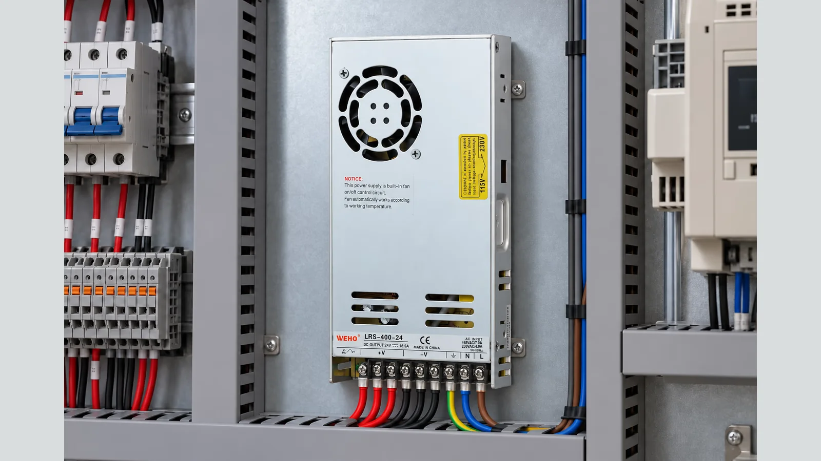
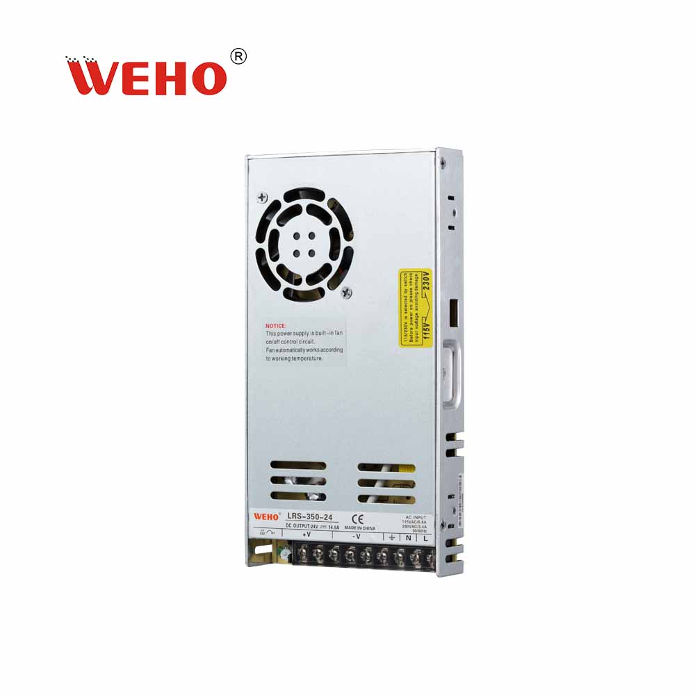
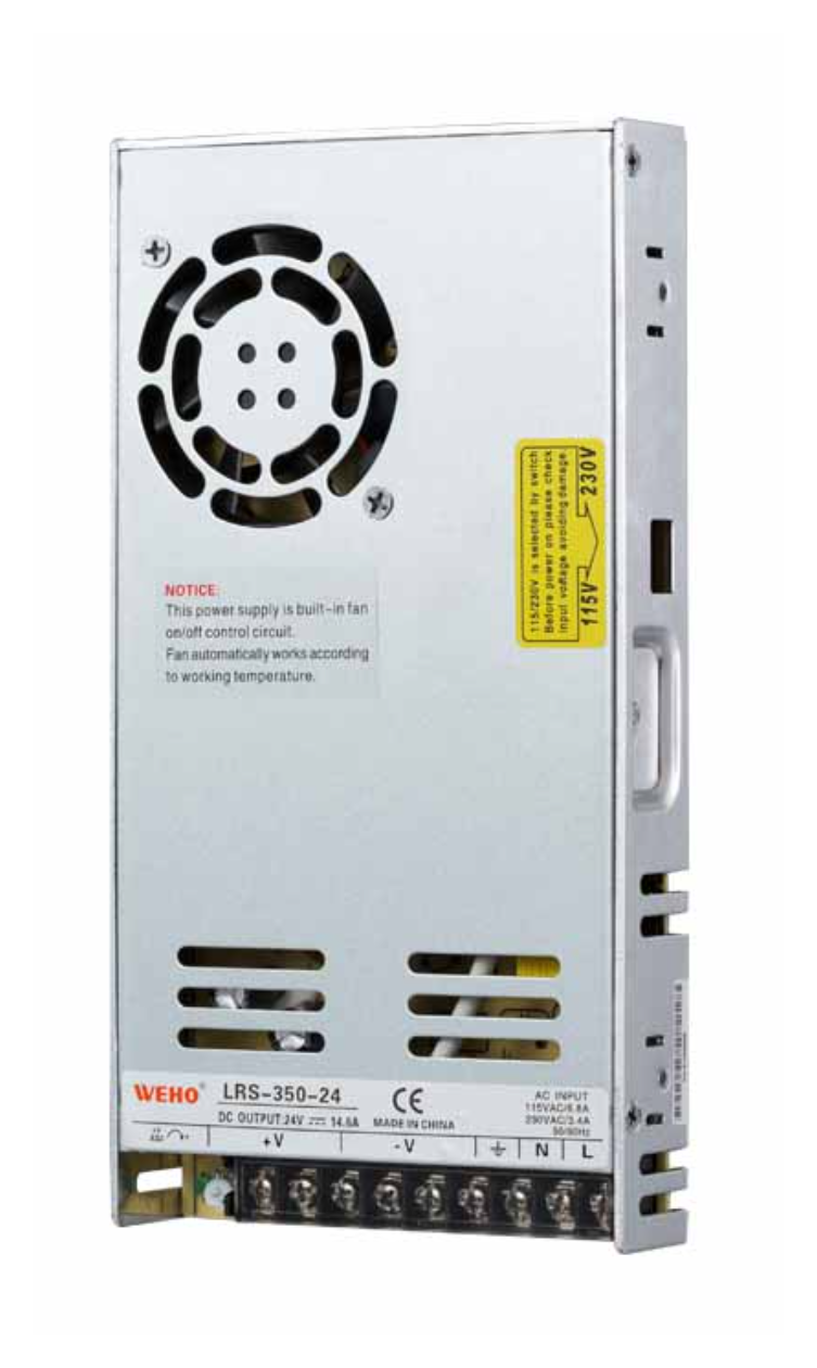
A connection review can start with the WEHO LRS-350-24 product identity, its published terminal assignments and the full product photograph. The repeated output markings are not permission to place multiple conductors in one terminal or a guarantee of current sharing. Obtain the applicable terminal and conductor instructions for the ordered unit; keep the path-resistance calculation separate from those assembly permissions.

Send WEHO the proposed source model, load-current states, allowed voltage at the load and the path-resistance record. Keep conductor selection, terminals and protection with the responsible assembly engineer while reviewing the supply’s own operating limits.