Adjacent photoelectric sensors can interfere when light from one installation reaches another receiver and changes its response. Compare each sensor operating alone with the complete installation under the real target and background conditions before deciding whether optical cross-talk is the cause.

Test one sensor and the complete arrangement
This is a diagnostic plan, not a claim that all close sensors interfere or that a particular spacing solves every installation. OMRON’s through-beam FAQ addresses mutual interference and notes that a neighboring emitter can affect a receiver. Its specific distances, filters and device arrangements belong to its own models and should not be copied to WEHO units.
Identify the sensing mode and application
Record every complete sensor model, sensing mode, mounting position, controller input and current settings. Through-beam, retroreflective and diffuse arrangements use different optical paths; background suppression or time-of-flight variants require their own documentation. Record which target triggers which output and the actual speed and orientation of the passing product.
ال WEHO C3Z-TOF2 product page identifies a diffuse TOF sensor; the manufacturer photograph identifies the product, while the lead image is an AI-assisted illustration of two mounted sensors. Neither image establishes a verified working installation. The OMRON through-beam example shows the class of question and does not establish a C3Z-TOF2 interference immunity rating or accessory compatibility.
Establish a single-sensor baseline
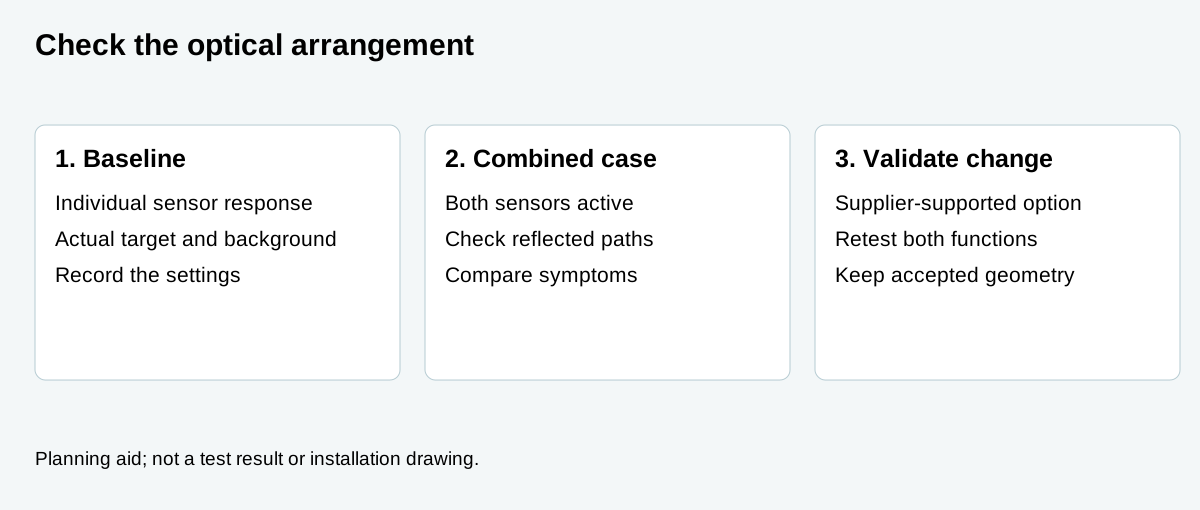
With the machine in an approved safe condition, ask the responsible technician to record each sensor’s response to target present and absent while other potentially interfering sensors are inactive. Preserve the target samples, position, speed, background, power conditions and output state. Repeat with each sensor in turn and note unstable or missing detections before considering other devices.
Then compare the same cases with other sensors operating. Keep geometry and samples unchanged so that the comparison is meaningful. If the issue occurs only in the combined arrangement, optical cross-talk is a hypothesis, not yet a proven cause: electrical noise, vibration, movement and changing ambient light may also produce intermittent symptoms.
Look for direct and reflected paths
Sketch the relative sensor and target positions. Light can reach a neighboring receiver directly or after reflection from a moving object, guide, machine surface or background. Review each credible configuration, including the absence of a target and the position where a target diverts light toward the neighboring sensor.
A change that blocks one unwanted reflection may also block the intended target or make maintenance difficult. Review space, alignment, sample range and machine guarding together. Avoid publishing a generic distance, angle or sensitivity setting as a universal fix.
Record the comparison
| Case | إعدادات | سجل |
|---|---|---|
| Baseline A | First sensor active; other emitters inactive. | Present/absent response, target and background. |
| Baseline B | Second sensor active; other emitters inactive. | Same sample and output evidence for second sensor. |
| Combined | Both active at actual mounting positions. | Compare wrong triggers, missed targets and timing. |
| Reflections | Representative target positions, surfaces and product variations. | Which cases alter the result and which do not? |
| Recheck | Documented change supported by each manufacturer. | Both intended detection and remaining false triggers. |
The table is a proposed comparison record. It is not an automatic installation instruction or result for the pictured sensor.
Review changes with the exact supplier
Depending on the actual model, the supplier may offer a supported change to orientation, shielding, distance, sensitivity, timing or a dedicated interference-prevention option. Verify that feature in the exact documentation before relying on it. Do not assume independent synchronization, a compatible optical filter or immunity to nearby sensors.
After any change, repeat the single and combined observations with actual target samples, background and relevant production positions. Check that both missed detections and false detections are covered. Save the accepted settings, bracket position, sample and revision so that a replacement sensor can be checked against the same arrangement.
Questions buyers ask
Do adjacent sensors always interfere? No. The result depends on the sensing mode, optical geometry, environment, models and their actual settings.
Does a sensor operating correctly by itself prove the pair works? No. It establishes a baseline; verify simultaneous operation with the actual targets and backgrounds.
Can a spacing rule from another brand be applied to C3Z? No. Obtain the exact-model documentation and validate the real arrangement.