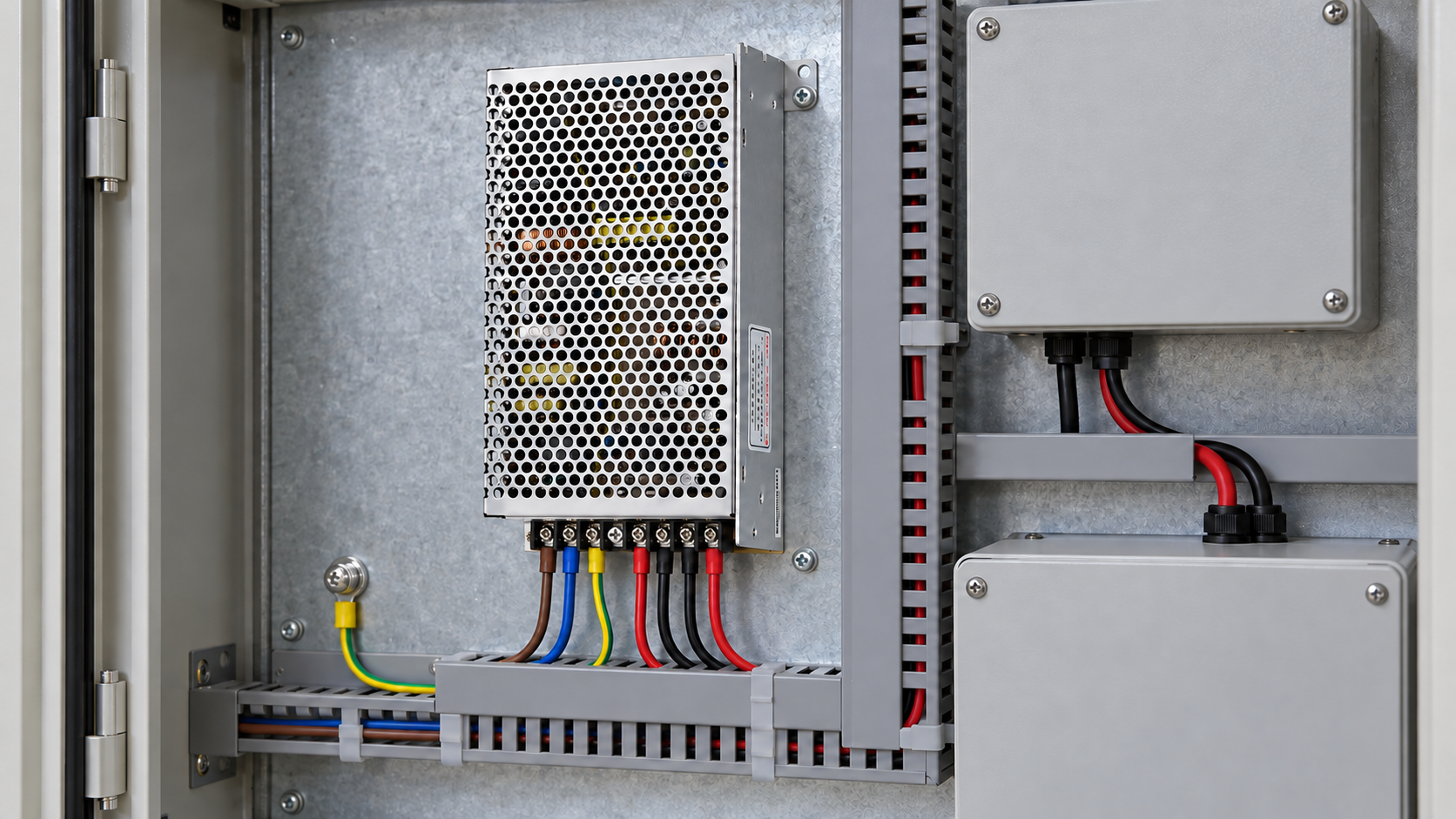
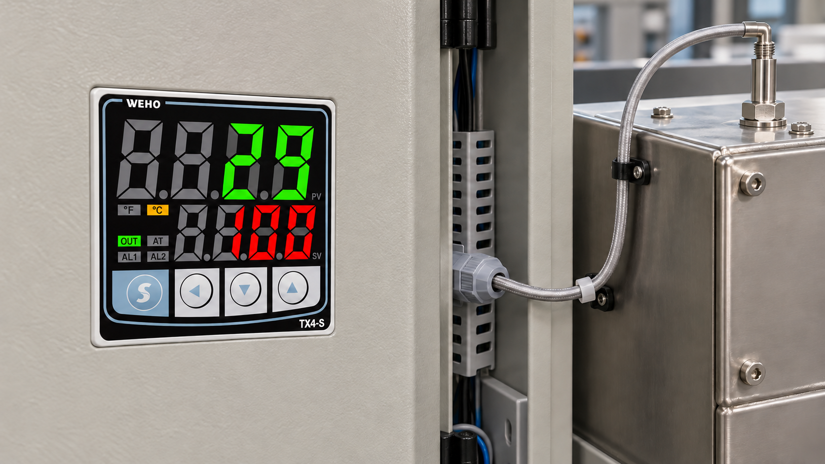
Direct answer: A two-wire sensor can draw a small current even when it is OFF. If that current keeps the PLC input above its guaranteed OFF condition, the input may remain ON. Compare the sensor’s maximum OFF-state leakage with the actual input’s documented OFF-current and voltage limits, then separately check ON-state voltage and current. A sensor indicator alone does not prove what the PLC input receives.
Why can the sensor be OFF while the PLC is ON?
A two-wire electronic sensor shares its load circuit with its own operating electronics. Its OFF state is not necessarily an open circuit. Rockwell’s sensor interface guide identifies OFF-state leakage as a reason an input may stay energized. The actual result depends on the receiving module’s input circuit, voltage, threshold, leakage conditions and wiring—not simply the sensor’s nominal supply voltage.
Compare the documented worst cases
| Check | Hypothetical values | Decision |
|---|---|---|
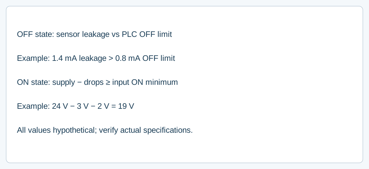
| OFF current | Sensor maximum leakage 1.4 mA; PLC guaranteed OFF at or below 0.8 mA | 1.4 > 0.8 mA: OFF is not guaranteed |
| Alternative OFF current | Another sensor maximum 0.3 mA; same 0.8 mA input OFF condition | 0.3 < 0.8 mA: current screen passes; check voltage and conditions too |
| ON input voltage | 24 V supply − 3 V sensor drop − 2 V wiring drop = 19 V; input requires 15 V minimum | 19 V ≥ 15 V: this voltage screen passes only under the stated conditions |
These numbers are illustrative, not WEHO product ratings. Check that each specification is valid at the actual operating voltage, temperature, polarity and load. A PLC can specify both OFF voltage and current; neither comparison alone substitutes for the module’s complete input specification. ON also requires the sensor’s minimum and maximum load current and the PLC input current to be compatible.
What about several sensors?
When two-wire sensors are paralleled, their OFF-state leakage can add at the common input. In series, available operating voltage and each sensor’s start-up behavior need review; the switching sequence can also affect the result. Omron discusses these model-dependent issues in its sensor series/parallel FAQ. Do not transfer its permitted quantities or specific circuit conditions to another manufacturer’s sensor.
A practical fault-isolation sequence
- Identify the exact sensor output type, rated supply, wire configuration and the PLC input module, common reference and input polarity.
- Check the supplier’s worst-case leakage and ON-state residual voltage at the relevant operating conditions, along with minimum and maximum load current. Confirm that the actual PLC input and any approved interface provide the sensor’s specified minimum ON-state load current.
- Read the PLC module’s guaranteed ON and OFF ranges and input current, including any filtering or diagnostics.
- Have a qualified person measure input voltage and current at the receiving terminals in the approved OFF and ON conditions, using the correct instrument and procedure. Record supply and load conditions.
- If margins are insufficient, ask the module and sensor suppliers about a compatible interface or an approved load arrangement. Any proposed resistor must be engineered for both states, its dissipation and temperature, component ratings, and device instructions; there is no universal resistor value.
- Repeat the check after cable, sensor quantity, input module or supply changes. Document any remaining undefined threshold region instead of treating a single successful test as a guarantee.
Where the power supply fits
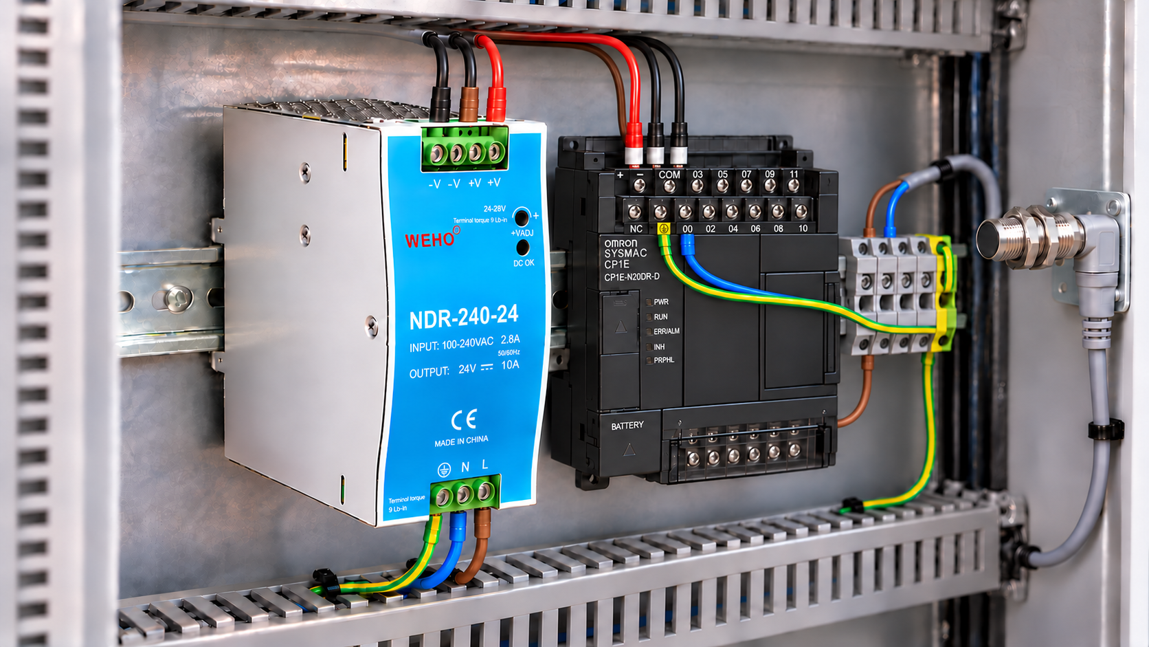
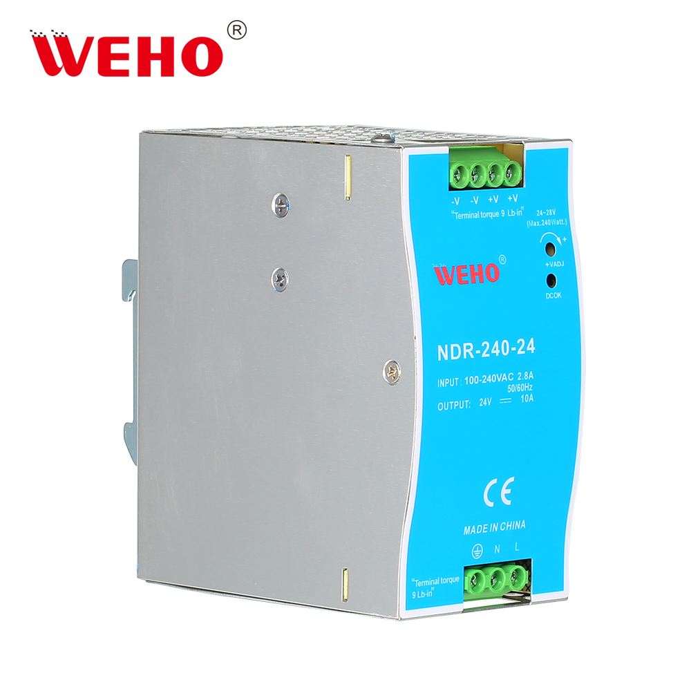
ال WEHO NDR DIN-rail power-supply range is relevant to a cabinet’s supply selection. The pictured NDR-240-24 is a power supply, not the two-wire sensor or PLC input being diagnosed. Its presence does not establish sensor-to-input compatibility. Obtain the actual sensor and PLC data sheets as well as the selected supply’s operating documentation.
Frequently asked questions
Does a lower leakage value automatically solve every problem?
No. It can improve the OFF margin, but the ON voltage, minimum load, input current, wiring polarity and actual environmental conditions still need verification.
Can I use an indicator LED instead of measuring the input?
No. The sensor indicator and the voltage/current at the PLC terminal represent different points in the circuit. Check both with appropriate, documented test methods.
Send WEHO the exact power-supply requirement and, for the interface review, the sensor and PLC input part numbers, wiring arrangement, supply tolerance and symptom. Request the applicable product documents before selecting components. تواصل مع ويهو.