



Key Engineering Takeaways
- A published product depth is not automatically its projection from the cabinet mounting plate.
- Identify the backplate, rail, clip, body and terminal reference planes before adding dimensions.
- The NDR-75-24 page lists 32 × 125.2 × 102 mm, but the reviewed drawing does not establish a complete mounted-depth datum chain.
- Obtain the missing reference definition or a traceable assembly measurement before releasing the installation envelope.
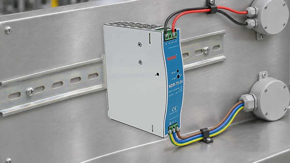
Why adding the rail height can double-count space
A cabinet layout uses the power supply’s published depth and adds the rail height. That result looks reasonable until a reviewer asks where the product-depth measurement begins. If the published dimension already includes some of the mounting relationship, the addition can count the same distance twice. If it excludes a clip feature, the result can also omit a real projection.
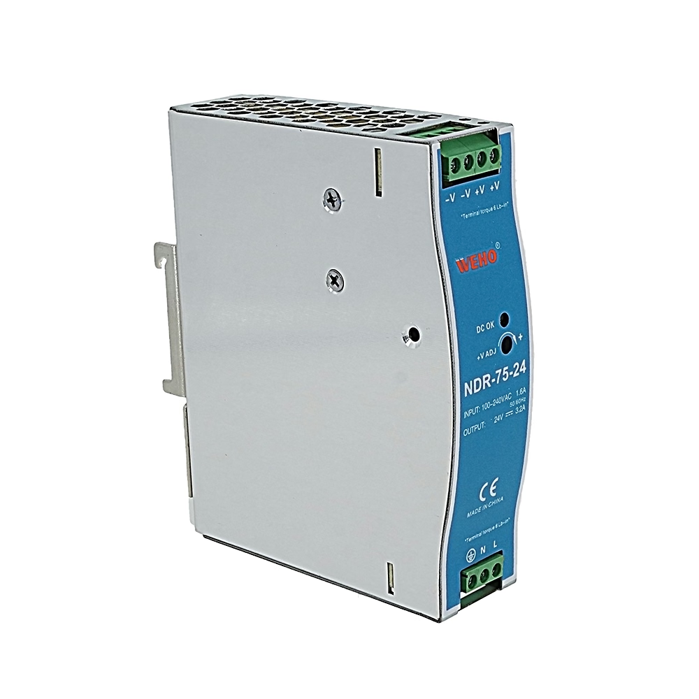
দ NDR-75-24 slim DIN supply is published with a 32 × 125.2 × 102 mm overall dimension entry and a 24 V, 3.2 A output rating. The linked mechanical illustration shows the body and mounting profile, but it does not label a complete backplate-to-front dimension chain.
The reader’s task is to define the mounted envelope correctly. It is not to find a generic clearance multiplier or assume that every DIN supply uses the same mounting depth reference.
Draw the reference planes before writing the sum
Name the surfaces involved in the actual installation. A practical drawing can identify the cabinet backplate, the relevant rail reference plane, the clip’s mounting relationship, the rear body reference and the frontmost feature being evaluated. Not every plane requires a separate positive allowance; some may coincide or already be included in another dimension.
Next, identify the endpoint. A body front, terminal screw, attached conductor or service-removal position can define different envelopes. State which one the depth calculation addresses. Calling them all “installation depth” hides the question the layout needs to answer.
Use a dimension ledger that records both endpoints of each value. A number with units but no reference surfaces cannot be placed reliably in the chain. Where a supplier drawing leaves the origin unclear, preserve that uncertainty until it is resolved.
Do not obtain an unlabelled depth by scaling the illustration on a screen. The drawing’s purpose may be identification or terminal assignment rather than a fully dimensioned installation model. A proportion measured from rendered pixels is not a substitute for a controlled dimensional definition.
Hypothetical datum-chain example
The following example is deliberately independent of the NDR-75’s published 102 mm entry. Suppose a hypothetical assembly has a measured 12 mm backplate-to-rail reference distance, 6 mm from that rail reference to a defined rear-body plane, and 98 mm from the rear-body plane to the body front.
The body-front projection is 12 + 6 + 98 = 116 mm from the backplate. If the required envelope includes an attached connector projecting another 8 mm beyond that body front, the assembly endpoint becomes 116 + 8 = 124 mm.
These invented dimensions demonstrate the method; they are not NDR-75 installation dimensions, rail requirements or conductor clearances. If a supplier instead provides one controlled rail-reference-to-front dimension covering the last two segments, use that dimension in place of those segments. Do not add both representations.
| Segment | Start plane | End plane | Example value | Evidence type |
|---|---|---|---|---|
| A | Backplate | Rail reference | 12 mm | Hypothetical assembly |
| B | Rail reference | Rear-body datum | 6 mm | Hypothetical assembly |
| C | Rear-body datum | Body front | 98 mm | Hypothetical assembly |
| D | Body front | Attached feature | 8 mm | Hypothetical assembly |

Swipe horizontally on a small screen, or open the full-size diagram.
Read the NDR-75 material within its actual scope
The reviewed NDR-75 illustration is useful: it shows the mounting profile and identifies terminal groups. It does not, by itself, tell the cabinet designer which rear reference plane defines the page’s 102 mm depth. That missing relationship prevents an evidence-based mounted-depth sum using that value.
The correct question to the supplier is specific: from which two planes is 102 mm measured, and does it include the mounting clip in the offered revision? Follow with the intended rail and backplate arrangement so the answer addresses the actual assembly.
| Available item | What it supports | What remains open | Next evidence |
|---|---|---|---|
| 32 × 125.2 × 102 mm PDP entry | Published overall-size screening | Depth reference and limits | Applicable dimensional definition |
| Mechanical illustration | Profile and terminal identification | Complete mounted-depth chain | Controlled mounting drawing |
| Selected rail documentation | Rail’s own geometry | Product-to-rail relationship | Matched mounting definition |
| Assembly measurement | Measured specimen and setup | Production tolerances | Agreed limits and identification |
The rail’s nominal description does not resolve the product’s datum. Nor does a photograph of the supply mounted on an unspecified rail. Identify the actual rail and any spacer arrangement, then verify how the product clip references that assembly.
Terminals and conductors need their own envelope where they affect the design. The terminal arrangement can be identified from the exact product material, but that does not provide a universal bend radius, strip length or service clearance. Obtain those requirements for the selected conductors, terminals and installation.
Release an installation envelope with traceable endpoints
- Identify the actual hardware. Record the exact supply suffix, offered revision, rail reference and any standoffs or spacers. Keep a picture or section sketch of the intended orientation. A catalog family description alone is insufficient for the final assembly model.
- Choose the envelope endpoint. State whether the decision concerns the body front, connected terminals, conductor route or removal path. If more than one matters, produce separate envelopes rather than folding all requirements into an unexplained extra depth.
- Label the dimension chain. Give every segment a start and end reference plane. Mark which dimensions come from supplier documentation and which are measured or hypothetical. Check that adjacent segments meet at the same plane without overlap or a missing interval.
- Resolve the published-depth datum. Ask what the NDR-75’s 102 mm entry includes and which drawing revision applies. Request dimensional limits where the layout depends on them. Do not assume a body dimension is a guaranteed maximum projection.
- Check the assembly when required. Measure the installed specimen against the defined reference planes using a suitable method. Identify the sample, rail, orientation and instrument. Preserve the distinction between a measured specimen and a supplier production limit.
- Update the layout and release scope. Attach the resolved chain to the cabinet model. Identify which envelope has been approved and retain separate open items for thermal spacing, wiring and service access. Review the chain again if the rail, clip version or mounting arrangement changes.
This method also makes a later substitution easier to assess. A proposed replacement can be compared at the same installed reference planes. Two products with different catalog-depth conventions can then be compared without silently changing what “depth” means between them.
Ask for the mounted-depth definition your drawing needs
Send WEHO the intended rail, backplate arrangement and labeled section sketch. Reference the NDR-75-24 published dimensions and ask which planes define the 102 mm entry, what mounting features it includes and which current drawing applies. Ask whether additional mechanical material is available without assuming a CAD resource is already offered.
Use the DIN installation datum-chain sheet to record source planes, endpoint planes and dimension status. Its numerical example remains explicitly hypothetical and must not be copied into an NDR-75 cabinet release.
Engineering FAQ
Can the NDR-75 depth be added directly to the rail height?
Not until the published depth’s reference planes are established. The addition may double-count or omit part of the mounting relationship. Ask which planes define the 102 mm entry and how the offered clip interfaces with the selected rail.
Does overall depth include connected conductors?
Do not assume it does. A catalog size can describe a product body or another defined envelope. Identify the source’s actual endpoints and create a separate connected-conductor envelope where the installation requires one.
Can a side-view image supply an unlabelled dimension?
No controlled dimension should be obtained simply by scaling a rendered image. Use a dimensioned applicable drawing or an identified assembly measurement. The illustration can help name features and reference planes without establishing an unprinted numerical value.
What changes require a new depth-chain review?
Review changes to the rail, spacers, mounting clip, product revision or evaluated front feature. Each can affect the reference relationship or envelope. Preserve the original chain so the reviewer can identify exactly which segment the change affects.



