A power supply short-circuit test needs more than a statement that the output survived. The useful engineering record identifies the fault actually applied, the current and voltage response while it remained present, and the behavior after it was removed. Those observations support different decisions.
On this page
This article is a test-plan and reporting framework for qualified laboratory personnel working under an approved procedure. The laboratory must select its fault fixture, ratings, protective measures and measurement methods for the equipment. The framework does not specify a live shorting method or authorize a fault outside the manufacturer’s permitted conditions.
Define the fault before choosing the acceptance rule
Start with the exact supply model and document revision. Identify what the manufacturer permits and what its short-circuit protection statement promises: the operating conditions, any duration or repetition restrictions, and the required recovery action. If those details are absent, resolve them before approving the test plan.
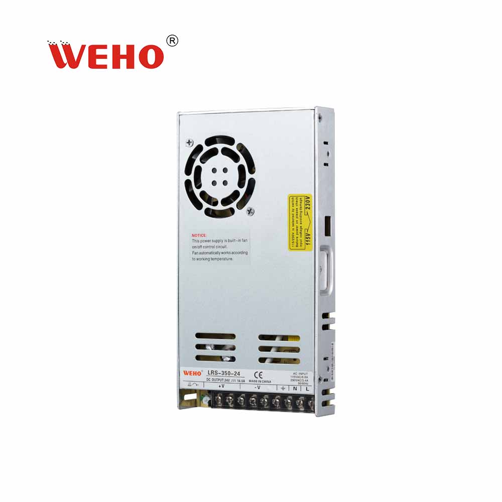
For a candidate such as the WEHO LRS-350-24, agree the permitted fault scenario against its applicable model documentation before testing. A protection entry in a model sheet does not replace the achieved-fault and recovery record described below.

TDK-Lambda’s overview of overcurrent protection describes several responses, including current limiting, shutdown and repeated restart attempts. That variety is the reason to use the specific supply documentation rather than assume that every short-protected unit has the same waveform or recovery behavior.
Separate an output short-circuit requirement from overload operation and from input-side fault ratings. A supply surviving an output fault does not, by itself, establish coordination with branch protection or a short-circuit current rating for the complete machine.
| Fault definition | What the approved plan should record | Why it affects interpretation |
|---|---|---|
| অবস্থান | Named terminals or equipment node, with the configuration drawing reference | The fault path and remaining connected loads can differ |
| Electrical path | Fixture identity and characterized path impedance or relevant resistance, including connections | A real fault is not an ideal zero-ohm node |
| Initial state | Already running or starting with the fault present; load and stored-energy state | Startup and running fault responses may differ |
| Exposure | Permitted fault duration, repetition count and recovery intervals | One event does not establish repeated-fault endurance |
| Release | The event used to declare fault removal and any permitted restart action | Recovery time needs a defined starting event |
Do not equate an electronic-load “short” with an ideal short
The fault implementation belongs in the report. A Keysight-hosted 6050A/6051A electronic-load manual provides a concrete example: its short operation is implemented differently in CV, CC and CR modes, and remains subject to instrument behavior and limits. That legacy example illustrates why the word “short” on an instrument is insufficient as a fault definition; it is not a recommendation for a current test fixture.
Use the manual for the actual instrument and range. Record whether its minimum operating voltage, current limit, short-mode characteristics, thermal protection or timing can alter the intended fault. If the load stops drawing current because its own protection acts, the trace may describe the instrument’s intervention instead of the supply’s intended response.
For a hypothetical measured point during a fault, 0.6 V across a defined path at 6 A corresponds to 0.6/6 = 0.10 Ω at that point. This is an interpretation of invented readings, not a recommended fault resistance. A single V/I value also does not characterize a time-varying, inductive or actively controlled path throughout the event.
Capture three stages on a common time reference
The record should make the pre-fault state, fault exposure and post-fault recovery visible. Identify measurement points and the bandwidth, sample rate, time base and current-sensor limits relevant to the question. Preserve a view that resolves fast events and one long enough to show repeated restart behavior or delayed recovery.
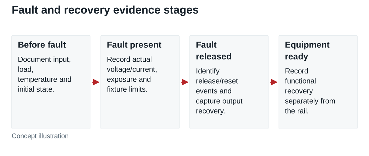
Before the fault, record the supply input condition, output voltage and current, connected equipment state and relevant temperatures. During the fault, retain the actual output voltage and current with the fault-state timing. Report peaks, repeated pulses and sustained portions separately when they matter; an average alone can hide the waveform.
After release, capture output recovery, any permitted reset or input-cycle event, and equipment status. Keep “the supply output recovered” and “the machine resumed its required function” as separate results. A controller that lost its state can require a different acceptance decision even when the rail returns normally.
Define recovery so two laboratories can report the same result
Consider an invented timing example. A laboratory declares fault removal at 250 ms. The output re-enters the application’s agreed band at 330 ms and remains inside it for the specified 10 ms confirmation interval. The electrical recovery declaration is therefore at 340 ms, or 90 ms after release. This definition includes the confirmation interval.
If the controller-ready event occurs at 410 ms, equipment recovery is 160 ms after release. A report that gives only “90 ms recovery” loses the distinction. The example values and intervals are not WEHO measurements or general limits.
If a reset is required, state whether recovery is measured from fault removal or from reset completion. Do not compare those values as though their starting events were identical. A unit that correctly requires an authorized reset may meet its documented protection behavior while still failing an application that requires automatic equipment recovery.
Use a decision table instead of a single pass label
| Question | Evidence needed | Result to record |
|---|---|---|
| Was the intended fault achieved? | Fixture characterization, actual voltage/current and duration | Valid, limited by fixture, or unresolved |
| Did the supply meet the agreed fault behavior? | Model-specific requirement and exposure traces | Pass, fail, or not assessed |
| Did output and equipment recover correctly? | Defined release/reset events, voltage and status records | Separate electrical and functional outcomes |
| Was post-test operation acceptable? | Agreed inspection and functional checks | Observed result within the test’s scope |
Hold approval if the fixture did not achieve the intended condition or an essential manufacturer restriction remains unknown. Retain failed attempts and instrument-limit events with the final report; discarding them can make the accepted record impossible to interpret.
Send WEHO the exact model, approved fault scenario, exposure limits and recovery requirement to discuss the documentation needed for a model-specific review.