Key Engineering Takeaways
- Average current supports an energy calculation at a fixed voltage.
- RMS current supports a resistive-heating calculation for the defined waveform.
- Check the instantaneous load voltage and supply requirements separately.
- Keep duty-cycle examples distinct from a product's documented overload capability.
Why can average current understate harness heating?
For a changing current, average resistive heating depends on the average of current squared. Squaring the average current can produce a lower result and miss the effect of repeated pulses. The engineering task is to assess the harness under the actual operating cycle while also checking the supply's instantaneous load requirements.
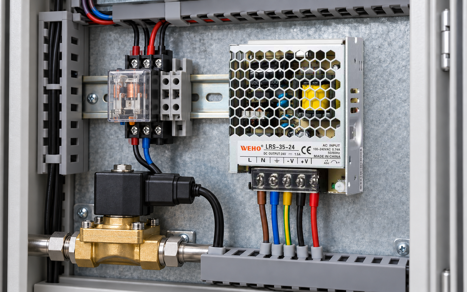
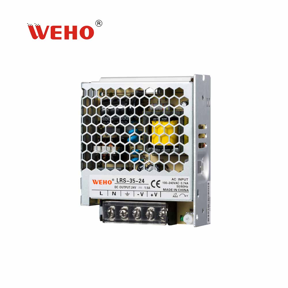
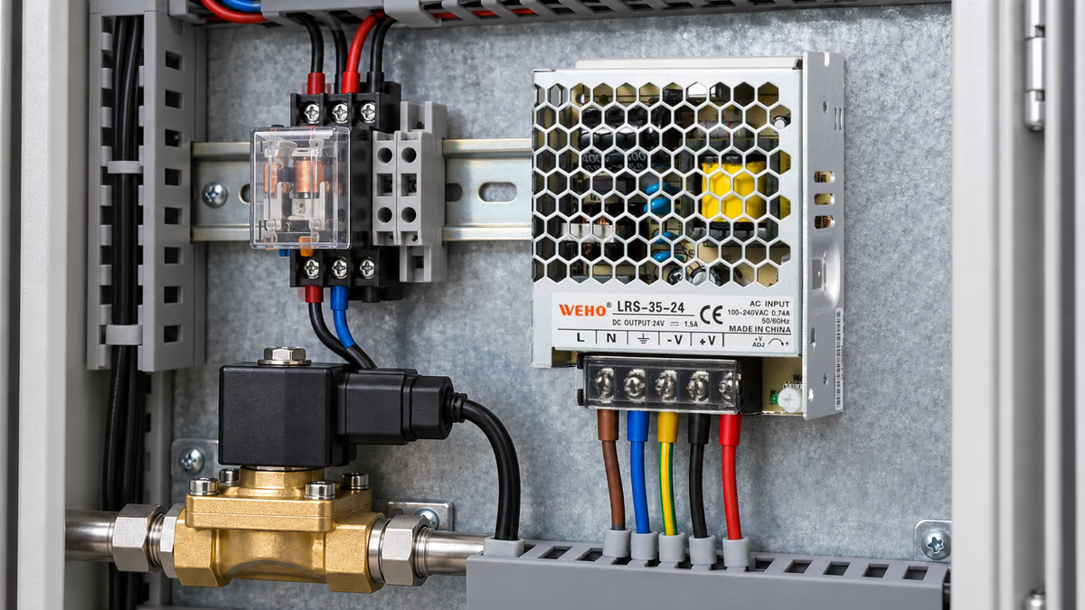
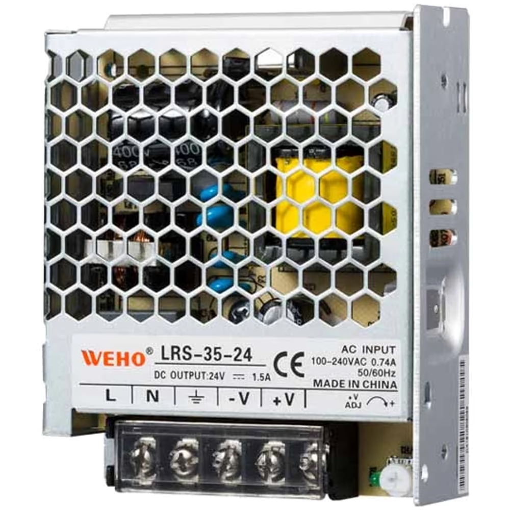
দ LRS-35-24 supply product reference provides an enclosed 24 V candidate for this example. The numerical waveform below is hypothetical. It does not describe a measured LRS-35 output or grant an undocumented repetitive overload allowance.
A small industrial controller may alternate between an idle state and a brief actuator-on state. The purchasing record should retain both states and their timing. A single average-current number can be useful, but it cannot replace every electrical and thermal check.
How do you calculate average and RMS current?
For a two-state waveform, average current is Iavg = dIon + (1 − d)Ioff, where d is the fraction of the complete cycle spent in the ON state. RMS current is Irms = √[dIon² + (1 − d)Ioff²]. Both formulas require the actual defined cycle.
Standard Engineering Sizing Example
Assume a hypothetical 24 V load draws 1.00 A for 25% of each cycle and 0.25 A for the remaining 75%. Assume the current is constant within each state, the waveform repeats, and the defined harness segment has a constant resistance of 0.20 Ω. These are calculation inputs, not manufacturer limits.
Average current is 0.25 × 1.00 + 0.75 × 0.25 = 0.4375 A. At an assumed constant 24 V load voltage, average load power is 24 × 0.4375 = 10.5 W. This power result describes energy demand within the stated approximation.
RMS current is √(0.25 × 1.00² + 0.75 × 0.25²) = √0.296875 = approximately 0.5449 A. Average resistive loss in the defined segment is Irms²R = 0.296875 × 0.20 = 0.059375 W, approximately 0.0594 W.
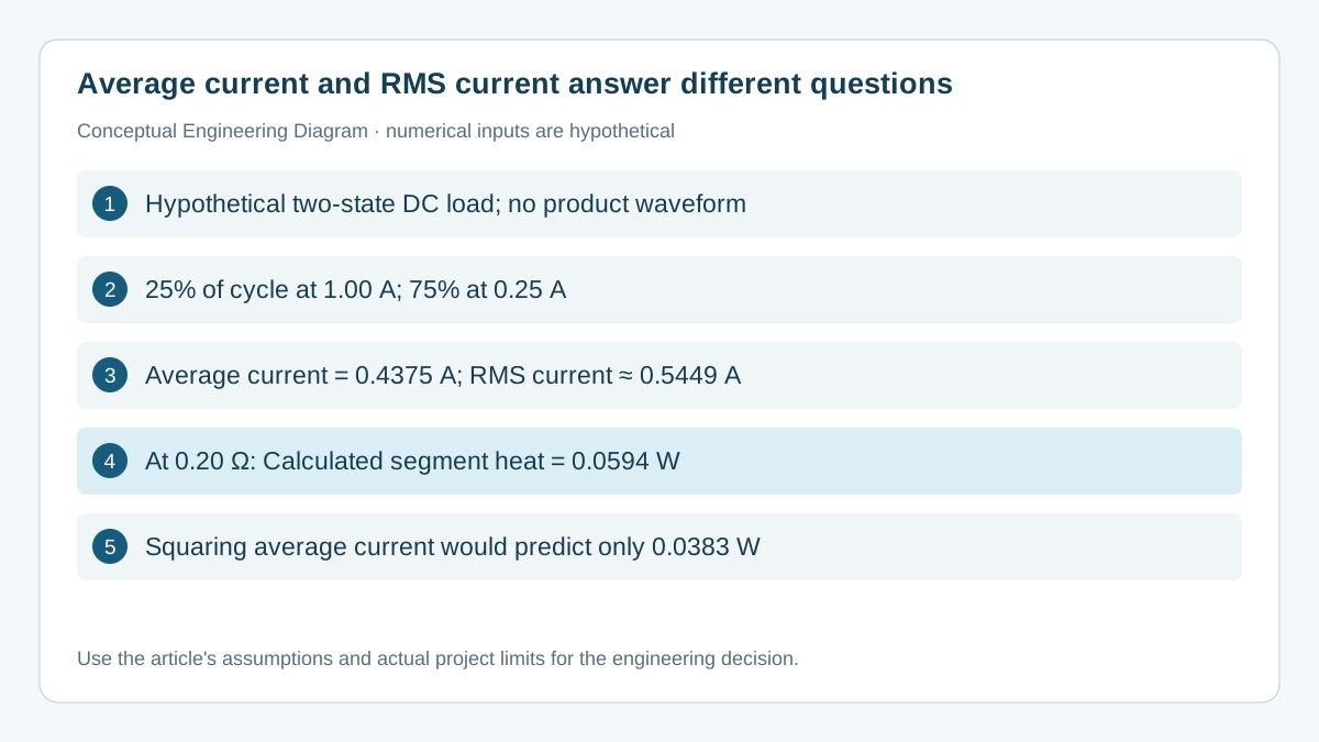
Squaring the average instead gives 0.4375² × 0.20 = approximately 0.0383 W. That is lower than the correct result for the assumed waveform. The difference occurs because the high-current part of the cycle contributes disproportionately to I²R heating.
The two state-specific losses provide a cross-check. At 1.00 A the segment dissipates 0.200 W; at 0.25 A it dissipates 0.0125 W. Weighting those losses by their cycle fractions gives 0.25 × 0.200 + 0.75 × 0.0125 = 0.059375 W, matching the RMS calculation.
Which quantities belong in the load-cycle matrix?
Keep peak or state current, average current and RMS current as different fields. The appropriate quantity depends on the decision. A current waveform with the same average as another waveform can have different resistive heating, instantaneous voltage drop and source requirements.
| Quantity | Hypothetical result | Useful decision | Does not prove |
|---|---|---|---|
| High-state current | 1.00 A | Instantaneous demand and drop | Repetitive overload permission |
| Average current | 0.4375 A | Average energy at fixed voltage | Resistive heating by itself |
| RMS current | 0.5449 A | Average I²R loss | Contact temperature or source transient response |
| Segment loss | 0.0594 W | Defined segment’s heat input | Complete harness qualification |
The instantaneous drop across the assumed segment is 1.00 A × 0.20 Ω = 0.20 V during the high state, and 0.25 A × 0.20 Ω = 0.05 V during idle. A load with a narrow operating window might care about the 0.20 V event even when the average power is modest.
Do not derive a component temperature directly from the calculated loss. Temperature depends on geometry, material, contacts, neighboring loads, enclosure conditions and time behavior. Use the applicable component evidence and the representative assembled thermal evaluation for the actual acceptance decision.
How should an OEM validate a repeating DC load?
Record current and voltage with enough time resolution to capture the required cycle. A slow averaging meter can hide short peaks or transitions. The necessary instrument bandwidth, capture window and measurement method depend on the actual event and decision.
- Identify every relevant state, its duration and the conditions that can change the sequence. Include maintenance or software modes that alter repetition.
- Record current through the defined harness segment and voltage at the load. Keep measurement points and instrument settings with the waveform.
- Calculate average current, RMS current and state-specific drop using the captured or justified waveform. Include all states over the complete period.
- Compare source demand, conductor/contact requirements and load voltage with their own applicable limits. Do not substitute one calculation for the other checks.
- Verify the representative assembled condition and record the acceptance method. Reassess after a load, harness, component or cycle change.
If the waveform contains a short charging or switching transient, include it where it contributes to the required quantity. A two-level approximation that omits that event may not represent the actual cycle. Report the approximation and its limits rather than silently calling a simplified trace a measurement.
Changes to energized conductors and access to mains terminals require qualified personnel and the applicable isolation procedure. Current measurement can also introduce burden or alter a connection event. Use a suitable method for the system rather than inserting a meter without assessing the effect.
What does RMS current leave unresolved?
RMS current is not a blanket power-supply selection rule. A source can have adequate average output capacity while failing an instantaneous load, startup or protection requirement. The LRS-35-24 operating documentation must still support the required load under its applicable input, temperature and installation conditions.
A resistive-loss calculation also does not establish suppression behavior for an inductive actuator. Turn-off voltage, release time and the destination of stored energy require their own circuit review. Keeping those questions separate prevents an acceptable RMS result from being interpreted as complete actuator compatibility.
Repetition rate matters when determining temperature cycling and response. Two cycles can have the same duty fraction and RMS current but different on-time duration. Their long-term average resistive heat may match under the model, while their temperature excursions and load behavior differ.
Retain the source of the resistance value. It should correspond to the segment actually being evaluated, including relevant conductors and contacts. If resistance changes materially with temperature, a constant-resistance calculation is only an approximation and should be refined or supported by representative measurements.
What should an OEM send WEHO for a pulsed-load review?
Send the required 24 V operating window, high and idle currents, state durations, repetition rate, startup behavior and operating environment when discussing the LRS-35-24 supply candidate. Include the load-terminal waveform and relevant harness details. Ask for applicable product documentation before approving the assembly.
Engineering FAQ
Can average current be used to calculate cable heating?
For a changing current, use the average of I²R or the corresponding RMS current when resistance is treated as constant. Squaring average current can understate loss. A steady current is the special case where average and RMS values coincide.
Does RMS current determine the required supply output rating?
Not by itself. Check the instantaneous current, duration, startup and allowed operating conditions as well as average demand. RMS is useful for a defined resistive-heating question, not a substitute for the source's documented load envelope.
Are the example's currents measured LRS-35-24 performance?
No. They are hypothetical load states used to demonstrate the calculation. The article does not report a product test, define a repetitive overload rating or establish a particular actuator's compatibility.
Can two pulses with the same duty cycle have different thermal behavior?
Yes. Their average resistive loss may match in a simplified model, while pulse duration and repetition affect temperature excursions and time response. Evaluate the quantities required by the actual component and equipment limits.
Does a low calculated harness loss prove that the contact is good?
No. A calculation depends on its resistance assumption and boundary. A damaged or poorly terminated contact can behave differently. Check the representative assembly, applicable component requirements and measured results before accepting the connection.